Conductor terminal

Active Publication Date: 2022-01-27
WAGO VERW GMBH
View PDF3 Cites 0 Cited by
  • Summary
  • Abstract
  • Description
  • Claims
  • Application Information

AI Technical Summary

Benefits of technology

[0004]It is therefore an object of the present invention to further impr

Problems solved by technology

For example, if an electrical conductor having a correspondingly large cross section is clamping at the clamping point, the clamping spring ma

Method used


Image

  • Conductor terminal
  • Conductor terminal
  • Conductor terminal

Examples


Embodiment Construction

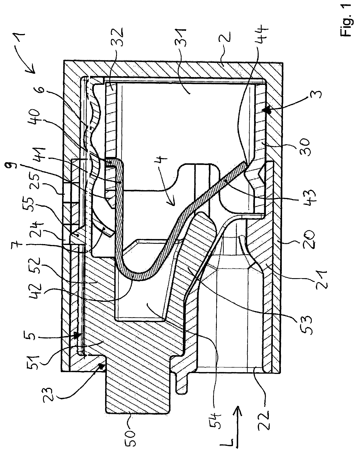
[0040]FIG. 1 shows a conductor terminal 1, including an insulating housing 2. Insulating housing 2 may be have a two-part design, including a main housing part 20 and a closure part 21 insertable into main housing part 20. Such an at least two-part design of insulating housing 2 makes it easier to install the contact insert and further components into insulating housing 2.

[0041]Insulating housing 2 has a conductor insertion opening 22 for inserting an electrical conductor in a conductor insertion direction L. Conductor insertion opening 22 may be, for example, part of closure part 21. Insulating housing 2 further has an actuating opening 23, through which an actuation of an actuating element 5 may take place or through which actuating element 5 may extend. Actuating opening 23 may be, for example, part of closure part 21.

[0042]An electrical contact insert is installed in the interior of insulating housing 2, which includes a busbar 3 and a clamping spring 4. Busbar 3 has a contact s...


PUM


Abstract

A conductor terminal, including an insulating housing, the insulating housing having a conductor insertion opening for inserting an electrical conductor in a conductor insertion direction, including a busbar and including a clamping spring, the clamping spring having a contact leg for contact with a part of the conductor terminal, the contact leg transitioning into a spring bend, and the spring bend transitioning into a clamping leg, the clamping leg forming a clamping point with the busbar for the electrical conductor, and including an actuating element, the actuating element being configured to open the clamping point, the actuating element being able to be transferred from an initial position into an actuating position, and the clamping point being opened in the actuating position.

Description

[0001]This nonprovisional application claims priority under 35 U.S.C. § 119(a) to German Patent Application No. 20 2020 104 276.9, which was filed in Germany on Jul. 24, 2020 and which is herein incorporated by reference.BACKGROUND OF THE INVENTIONField of the Invention[0002]The present invention relates to a conductor terminal, including an insulating housing, the insulating housing having a conductor insertion opening for inserting an electrical conductor in a conductor insertion direction, including a busbar and including a clamping spring, the clamping spring having a contact leg for contact with a part of the conductor terminal, the contact leg transitioning into a spring bend, and the spring bend transitioning into a clamping leg, the clamping leg forming a clamping point with the busbar for the electrical conductor, and including an actuating element, the actuating element being configured to open the clamping point, the actuating element being able to be transferred from an ...

Claims


Application Information

Patent Timeline
IPC IPC(8): H01R4/48H01R9/24
CPCH01R4/4836H01R9/2416H01R4/4827H01R4/48H01R4/48185H01R4/48365H01R4/48275
Inventor TUERKEKOELE, MUHAMMET ALIAHLDAG, JOERG
Owner WAGO VERW GMBH
Why Eureka
Try Eureka