Fixation screw & method

a fixing screw and screw technology, applied in the field of improved wedging cages and fixing screws, can solve the problems of large annual expenditure, significant challenge, and loss of productivity

Pending Publication Date: 2022-02-03
CTL MEDICAL CORP
View PDF0 Cites 1 Cited by
  • Summary
  • Abstract
  • Description
  • Claims
  • Application Information

AI Technical Summary

Benefits of technology

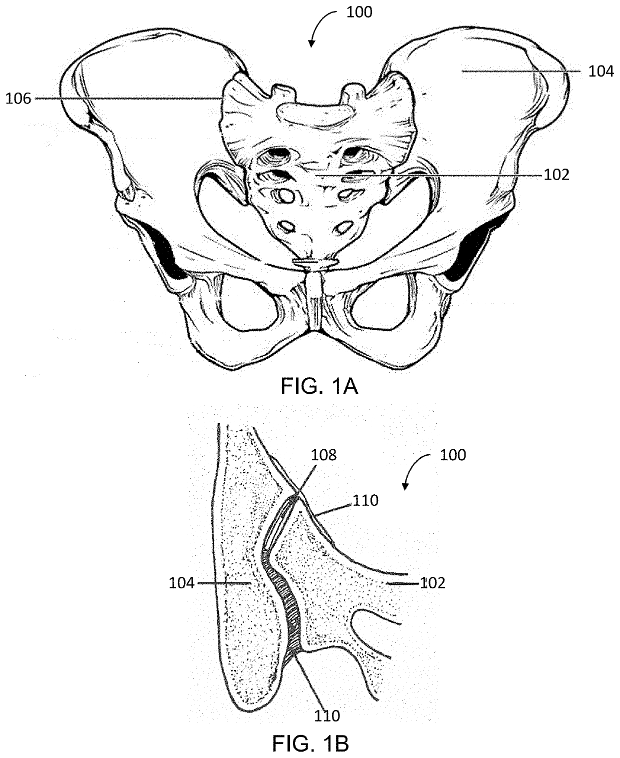
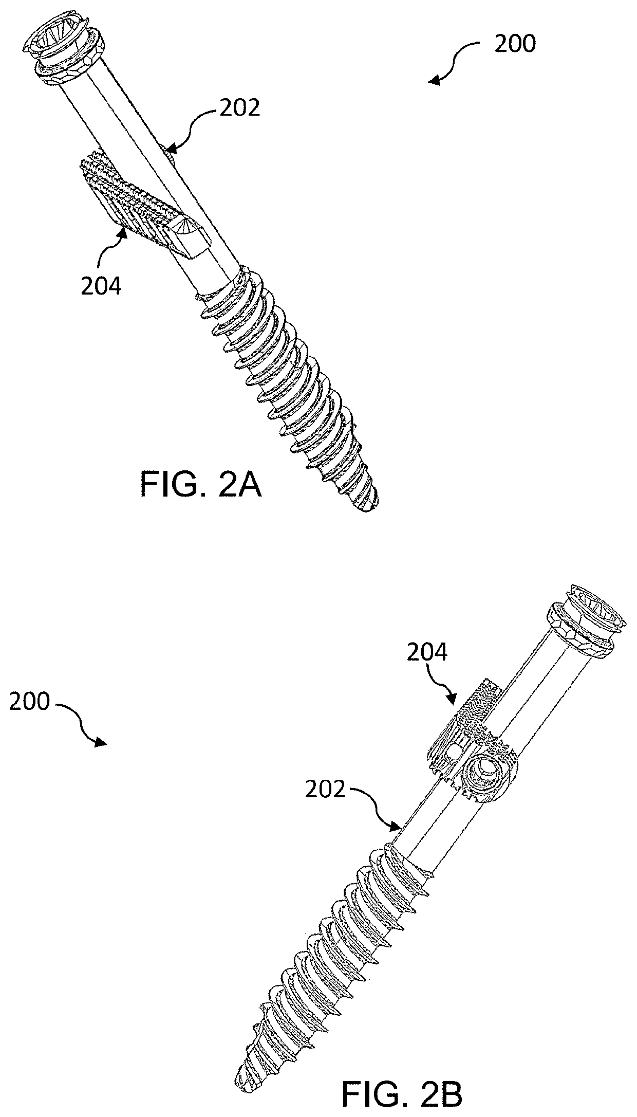
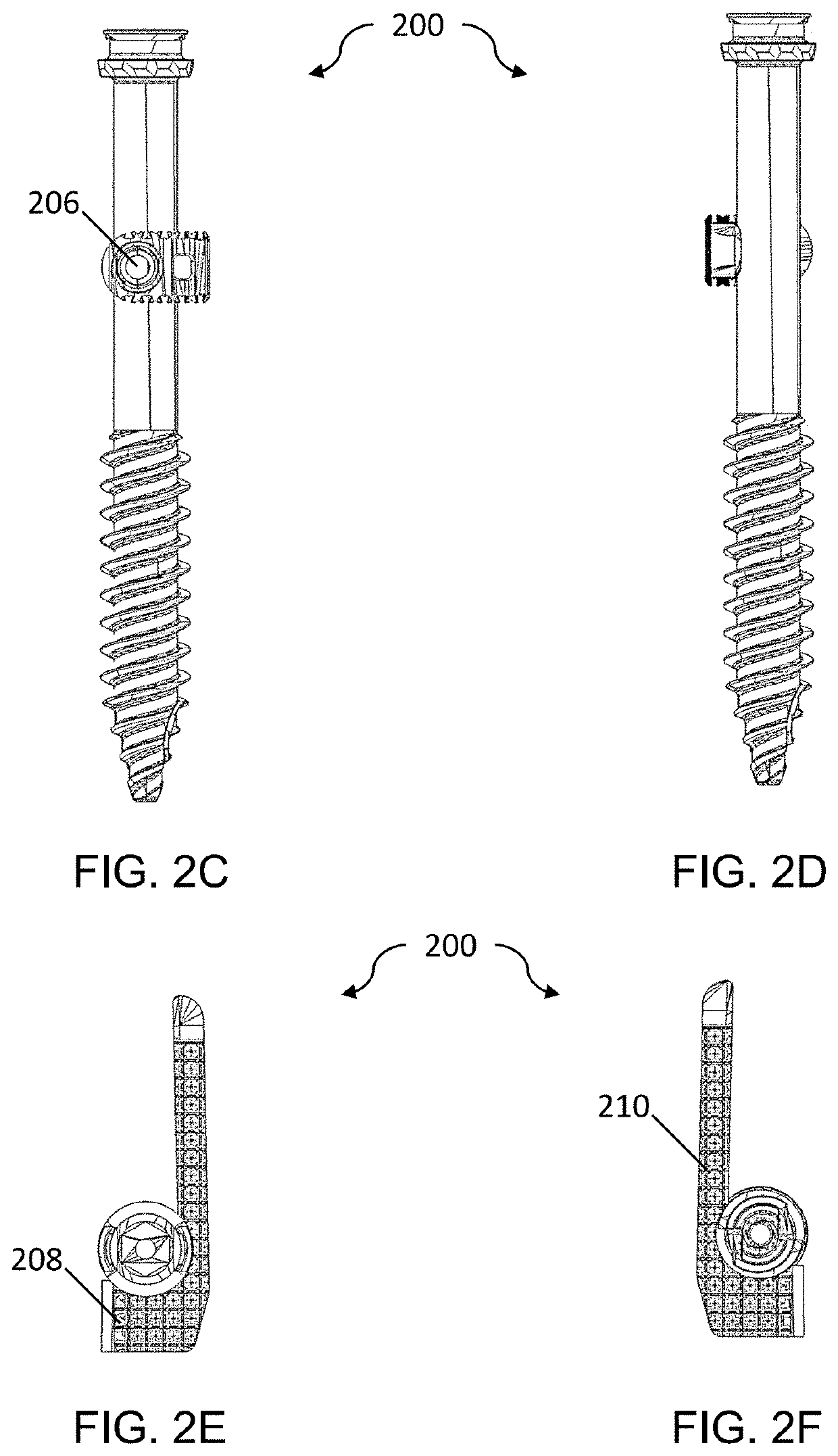
[0013]In another embodiment, the SI joint fixation system comprises an anchored wedging cage. The anchored wedging cage comprises a wedging cage and an anchor assembly. The wedging cage may comprise an A-shaped, a B-shaped, a C-shaped, H-shaped, I-shaped, L-shaped, O-shaped, U-shaped, a Y-shaped, and M or W shaped wedging cage and / or any combination thereof. The wedging cage may comprise at least one base, the at least one base includes a threaded bore. The anchor assembly comprises a plurality of pins and an anchor. The anchor comprises a shaft and at least two blades, the shaft comprising a channel, the channel is disposed around the circumference of the shaft. The channel is sized and configured to receive a portion of the plurality of pins. The anchor assembly is rotatable from an unlocked position to a locked position, the unlocked position has the at least a portion of the anchor mating with a portion of the wedging cage and it allows the wedging cage to move or slide within the SI joint. The locked position rotates the anchor anywhere between 1 degree to 90 degrees away from the portion of the wedging cage and allows the wedging cage to lock into place within the SI joint.

Problems solved by technology

Loss of productivity and income combined with medical expenses results in vast expenditures annually in the US related to low back pain.
Successful treatment of low back pain demands identifying the pain generator(s), which can be a significant challenge due to the multifactorial nature of this condition.
Despite the large number of patients with SI joint pain, treatment options have been limited to conservative care involving physical therapy and joint injections, and if conservative therapy fails, then SI joint fusion surgery is recommended.
However, the current SI fusion implants do not provide flexibility to the doctor during the operative procedure.

Method used


Image

  • Fixation screw & method
  • Fixation screw & method
  • Fixation screw & method

Examples


Embodiment Construction

[0062]The disclosure and the various features and advantageous details thereof are explained more fully with reference to the non-limiting embodiments and examples that are described and / or illustrated in the accompanying drawings and detailed in the following description. It should be noted that the features illustrated in the drawings are not necessarily drawn to scale, and features of one embodiment may be employed with other embodiments as the skilled artisan would recognize, even if not explicitly stated herein. Descriptions of well-known components and processing techniques may be omitted so as to not unnecessarily obscure the embodiments of the disclosure. The examples used herein are intended merely to facilitate an understanding of ways in which the disclosure may be practiced and to further enable those of skill in the art to practice the embodiments of the disclosure. Accordingly, the examples and embodiments herein should not be construed as limiting the scope of the dis...


PUM

PropertyMeasurementUnit
lengthaaaaaaaaaa
pore sizeaaaaaaaaaa
thicknessaaaaaaaaaa

Abstract

The invention discloses an improved wedging cage within the sacroiliac (SI) joint and fixation screw(s). The wedging cage is adapted to be positioned between the sacrum and the lilac bone (e.g., the sacroiliac joint), and the wedging cage is effective to receive one or more fixation or axial screws to fasten the wedging cage and secure the wedging cage to the adjacent pelvic bones to provide a combination effect of fusion and / or fixation. Accordingly, the improved fixation screw assemblies promote flexibility and adaptability due to the adjustable head being movable to a locked and unlocked position relative to the screw body when implanted onto a substrate.

Description

CROSS-REFERENCE TO RELATED APPLICATIONS[0001]This application is a continuation-in-part of U.S. application Ser. No. 16 / 797,861 entitled “Sacro-Iliac (SI) Joint Fixation System and Method,” filed on Feb. 21, 2020, which claims the benefit of U.S. Provisional Application No. 62 / 809,419 entitled “Wedging Plate,” filed Feb. 22, 2019, the disclosures of which are incorporated by reference herein in their entireties.[0002]This application also claims the benefit of U.S. Provisional Appl. No. 63 / 067,537 entitled “Wedging Plate Improvements,” filed on Aug. 19, 2020, the disclosure of which are incorporated by reference herein in its entirety.TECHNICAL FIELD[0003]The present invention relates to methods, devices, and systems for an improved wedging cage and fixation screw(s). More specifically, the improved wedging cage may allow the implantation of the wedging cage before screws are deployed and after screws are deployed.BACKGROUND OF THE INVENTION[0004]Low back pain (LBP) is exceedingly c...

Claims


Application Information

Patent Timeline
Patent Type & Authority Applications(United States)
IPC IPC(8): A61B17/70
CPCA61B17/7032A61B2017/00831A61B17/7055A61B17/7044A61F2/30988B33Y10/00A61B17/809A61F2/30767A61F2/4603A61F2002/30405A61F2002/30622A61F2002/3085A61F2002/3092A61F2002/30995B33Y80/00A61B2017/00893B22F5/06B22F5/106B22F10/25B22F10/28B22F10/14B22F10/62B22F2999/00A61F2002/4625A61F2002/30604A61F2002/30616A61F2002/30841A61F2002/30843A61F2002/30845A61F2002/30851A61F2002/30859A61F2002/30863A61F2002/30985A61F2002/30518A61F2002/30266A61F2002/30593A61F2002/30131Y02P10/25B22F2003/242
Inventor SUH, SEANSUH, JONTREZISE, ROB
Owner CTL MEDICAL CORP
Why Eureka
Try Eureka