Method and Apparatus For Dynamic Scoliosis Orthosis

a dynamic scoliosis and orthosis technology, applied in the field of scoliosis therapy braces, can solve the problems of heavy and bulky braces, many difficulties with the apparatus, and difficulty in performing normal functions, so as to improve the treatment and therapy of scoliosis

Inactive Publication Date: 2008-10-23
PREDICTIVE THERAPEUTICS +1
View PDF9 Cites 24 Cited by
  • Summary
  • Abstract
  • Description
  • Claims
  • Application Information

AI Technical Summary

Problems solved by technology

However, these generally involve heavy and bulky braces.
Furthermore these braces tended to be so large and restrictive that patients had difficulty performing normal functions while wearing them, or found the braces so uncomfortable or embarrassing that patients refused to wear them.
However many difficulties with the apparatus remained.
Traditional methods of using the brace are equally burdensome for users, and difficult for practitioners to implement.
Braces used are not adjustable, have a closed design which increases the brace's weight and heat retention.
Furthermore, because braces are not adjustable, users have the same treatment whether asleep, when more aggressive treatment is possible, and awake, when more aggressive treatment is very painful.

Method used


Image

  • Method and Apparatus For Dynamic Scoliosis Orthosis
  • Method and Apparatus For Dynamic Scoliosis Orthosis
  • Method and Apparatus For Dynamic Scoliosis Orthosis

Examples


Embodiment Construction

[0014]This specification describes exemplary embodiments and applications of the invention. The invention, however, is not limited to these exemplary embodiments and applications or to the manner in which the exemplary embodiments and applications operate or are described herein.

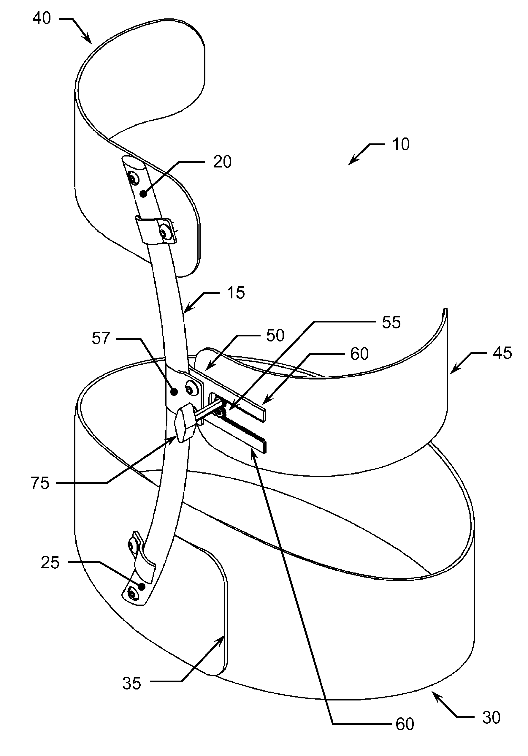
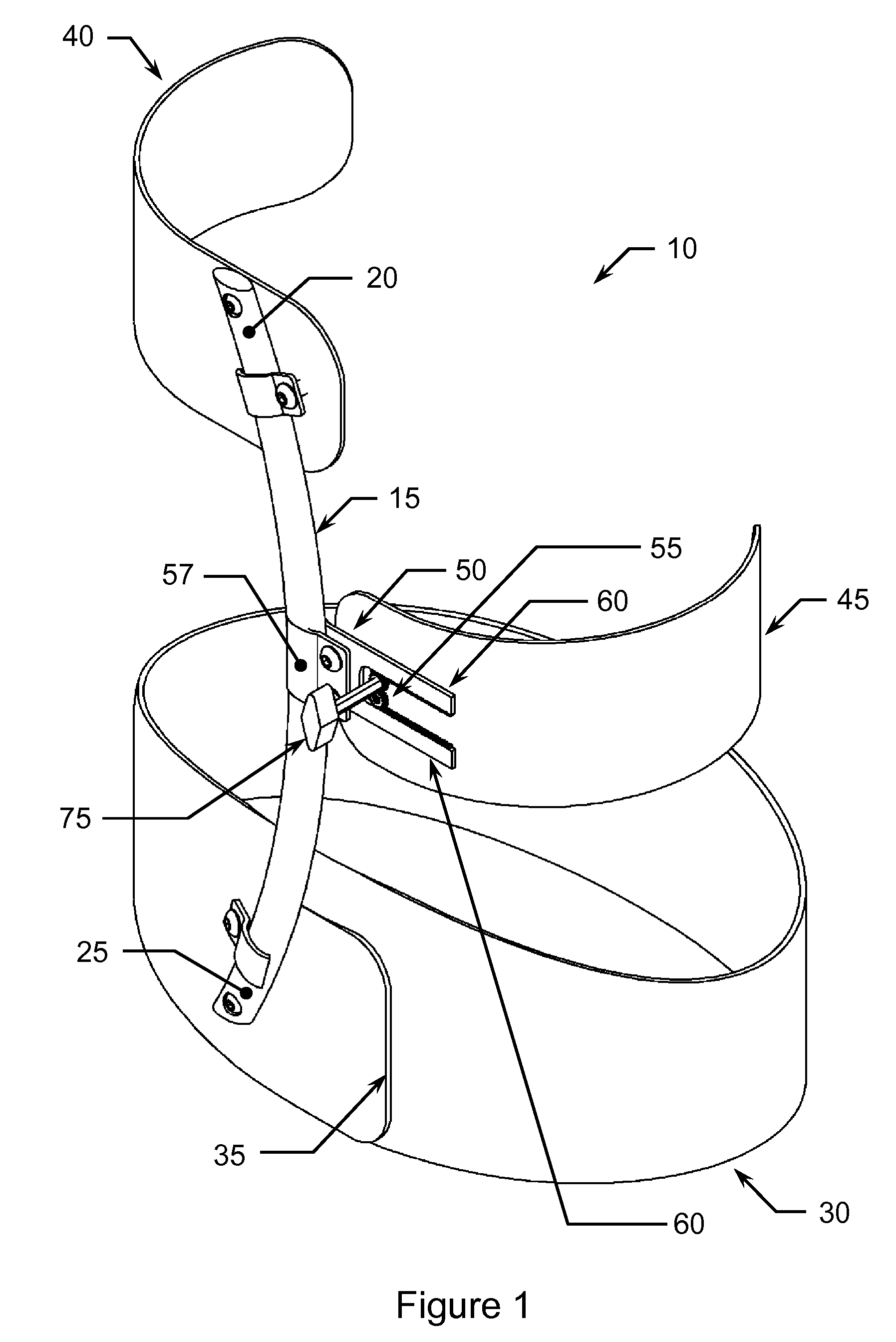
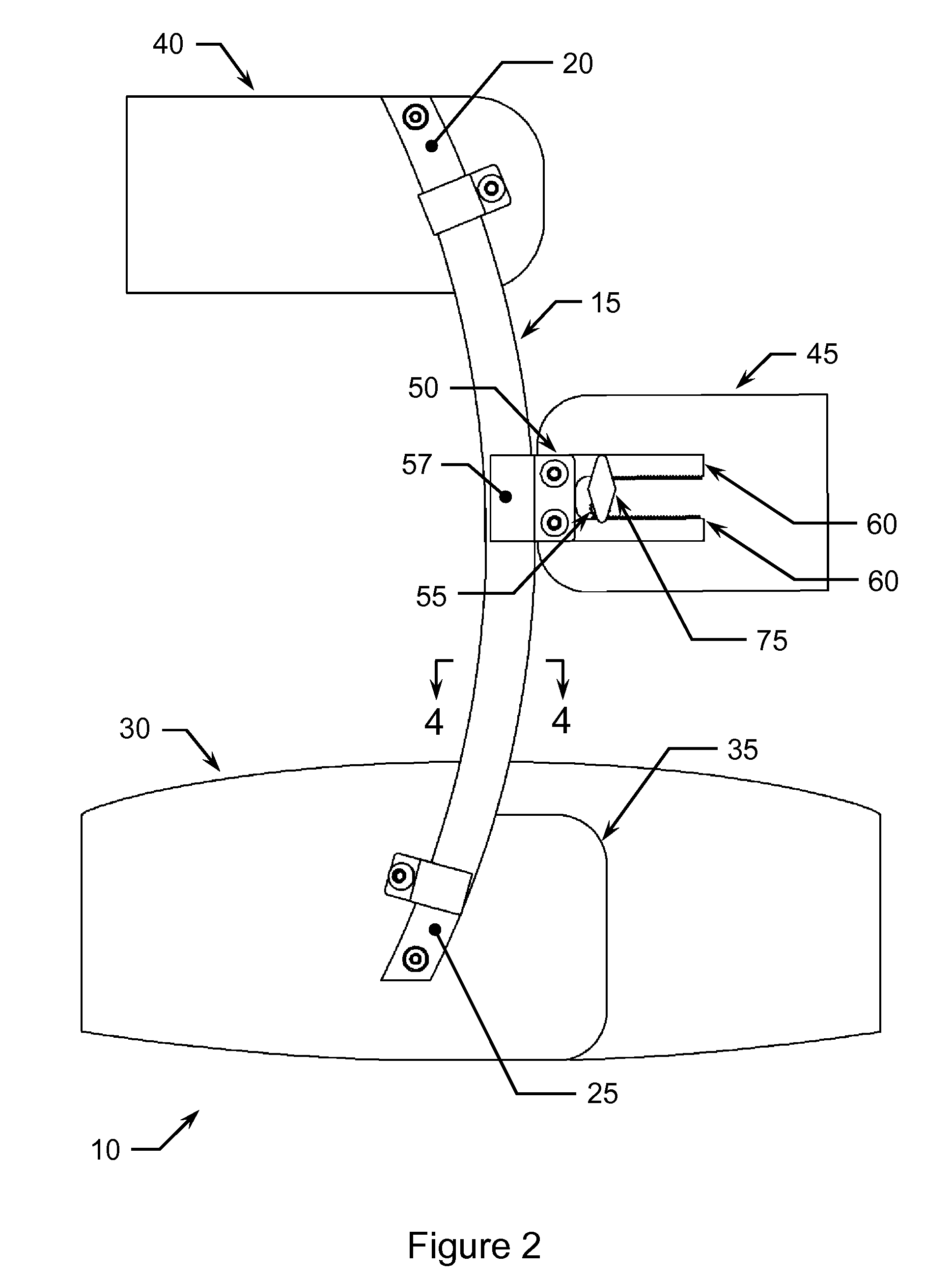
[0015]FIGS. 1 through 4 illustrate an exemplary embodiment of a Dynamic Scoliosis Orthosis or brace (or harness) 10. Brace 10 comprises a rod 15, a pelvic mold 30, an auxiliary pad 40, an apical pad 45, an extension arm 50, and an adjustment key 75. Rod 15 may be made of a variety of materials or composite of materials including metals such as aluminum, carbon fiber, polymers or fibers and resins. Ideally the material selected will provide a rigid and stable support for the harness, thus providing steady force on the curved spine. The exemplary embodiment of the invention teaches a carbon fiber rod because it is light weight, flexible and still extremely strong. Rod 15 has a general elliptical cross-sectiona...


PUM


Abstract

The invention is a three-contact-point dynamic scoliosis orthosis (DSO) brace to aid physicians treating scoliosis. A pelvic mold and two pads, one positioned above the apex of the spine curvature, the other positioned orthogonal to the apex of the spine curvature provide the anchor points on opposite sides of the curve. The pad orthogonal to the curve's apex is adjustable.

Description

CROSS REFERENCE TO RELATED APPLICATION[0001]This nonprovisional utility patent application is a continuation-in-part of and claims the benefit under 35 USC § 120 to co-pending U.S. patent application Ser. No. 12 / 150,475 filed Sep. 4, 2007, which is a continuation of and claims the benefit under 35 USC § 120 to co-pending U.S. patent application Ser. No. 11 / 784,180 filed Apr. 4, 2007, which is a continuation of and claims the benefit under 35 USC § 120 to co-pending U.S. patent application Ser. No. 11 / 588,188 filed Oct. 25, 2006, which is a continuation of and claims the benefit under 35 USC § 120 to co-pending U.S. patent application Ser. No. 11 / 416,625 filed May 2, 2006, which is a continuation of and claims the benefit under 35 USC § 120 to co-pending U.S. patent application Ser. No. 11 / 261,947 filed Oct. 28, 2005, which claims the benefit under 35 USC § 119(e) to co-pending U.S. provisional patent application No. 60 / 623,073 filed Oct. 28, 2004, all of which are incorporated in th...

Claims


Application Information

Patent Timeline
Patent Type & Authority Applications(United States)
IPC IPC(8): A61F5/00
CPCA61F5/024
Inventor OGILVIE, JAMES W.
Owner PREDICTIVE THERAPEUTICS
Why Eureka
Try Eureka