
Component manufacturing system and component manufacturing method

Pending Publication Date: 2022-02-10
YAZAKI CORP
View PDF8 Cites 0 Cited by
  • Summary
  • Abstract
  • Description
  • Claims
  • Application Information

AI Technical Summary

Benefits of technology

The patent text describes a system and method for manufacturing components, specifically wire harnesses. The technology prevents the vendor from having too much inventory and ensures that the customer always receives the necessary number of wire harnesses on time.

Problems solved by technology

However, when the component manufacturer imports the wire harness manufactured overseas from the overseas country into Japan and delivers the imported wire harness to a customer in Japan, it takes about 2 to 3 weeks from shipment of the wire harness in the overseas country to arrival thereof in Japan, such that the component manufacturer is required to consider a problem of the delivery date of the wire harness to be delivered to the customer.

Method used


Image

  • Component manufacturing system and component manufacturing method
  • Component manufacturing system and component manufacturing method
  • Component manufacturing system and component manufacturing method

Examples


first embodiment

Outline of Component Manufacturing System

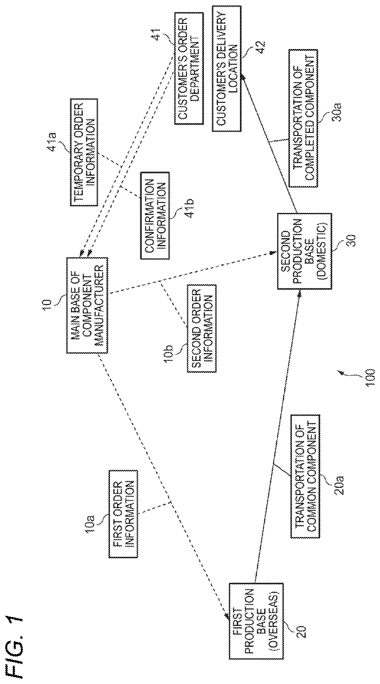
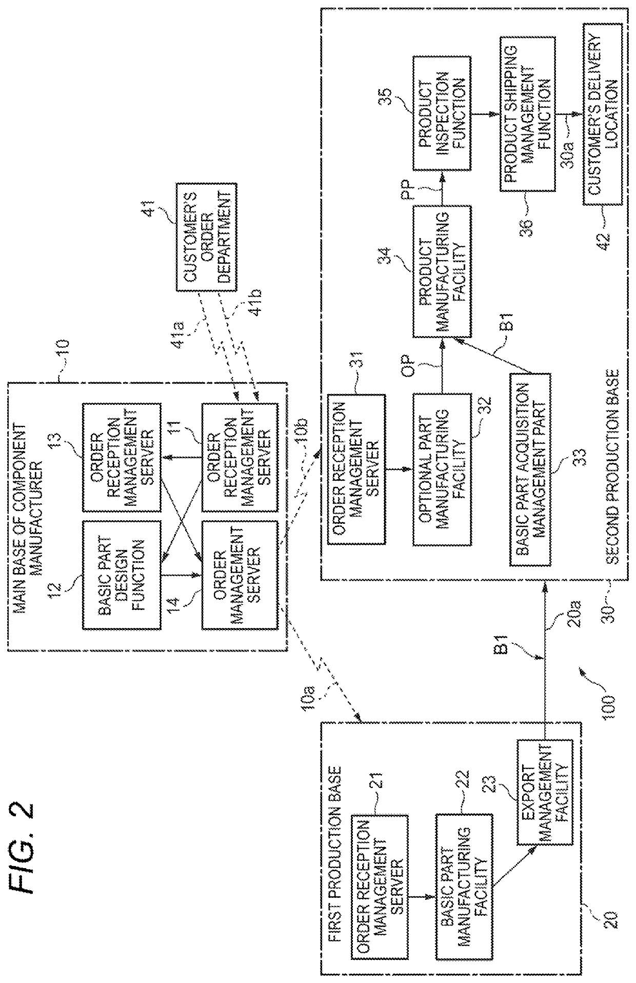
[0049]FIG. 1 illustrates a configuration outline of a component manufacturing system 100 according to a first embodiment of the present invention.

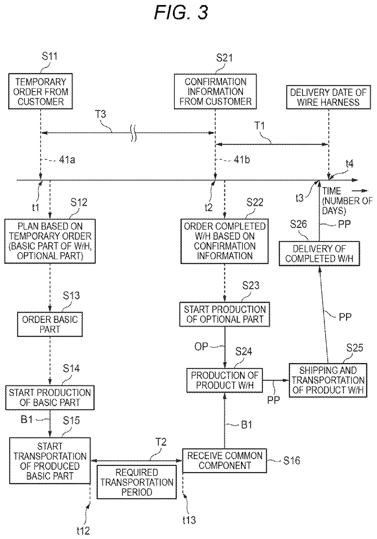
[0050]The component manufacturing system 100 illustrated in FIG. 1 is prepared to be used by a component manufacturer that manufactures a wire harness (W / H) which is a main component to be mounted on a vehicle such as an automobile or the like or an intermediate component thereof. The component manufacturer that manufactures the wire harness usually designs the wire harness based on plan information acquired from a customer, for example, a vehicle manufacturer, prior to the start of mass production of the vehicle. After that, when receiving an order for the wire harness every predetermined period, the component manufacturer manufactures the required number of wire harnesses that meet specifications designated by the customer, and delivers the manufactured wire harnesses to a designated delivery loca...

second embodiment

[0102]FIG. 4 illustrates a functional configuration example of a main part of a component manufacturing system according to a second embodiment of the present invention.

[0103]A component manufacturing system 100A illustrated in FIG. 4 is a modification of the component manufacturing system 100 illustrated in FIG. 1. The following description will be omitted for the same element as that of the component manufacturing system 100 represented by the same reference sign.

[0104]The component manufacturing system 100A illustrated in FIG. 4 includes a main body part 10A and a delivery part 10B of the main base 10 belonging to the component manufacturer, and the first production base 20, an intermediate base 50, and the second production base 30. That is, the delivery part 10B, which performs a procedure of delivering the wire harness PP of the product to the customer's delivery location 42, is separated from the main body part 10A of the main base 10 and exists as an independent department. ...


PUM


Abstract

A component manufacturing system includes a main base, a first production base and a second production base. The main base designs a common wire harness and optional wire harnesses. The main base has a first order function of determining the number of common wire harnesses to be produced based on temporary order information and placing an order with the first production base, and a second order function of acquiring order confirmation information from the customer at a timing closer to a delivery date than the temporary order information and placing an order with the second production base for the completed wire harness based on the confirmation information.

Description

CROSS REFERENCE TO RELATED APPLICATIONS[0001]This application is based on and claims priority from Japanese patent application No. 2020-133333 filed on Aug. 5, 2020, and Japanese patent application No. 2020-184391 filed on Nov. 4, 2020, the entire contents of which are incorporated herein by reference.TECHNICAL FIELD[0002]The present invention relates to a component manufacturing system and a component manufacturing method that can be used by a component manufacturer that manufactures a wire harness, which is a vehicle component, based on a customer requirement.BACKGROUND ART[0003]Generally, a wire harness mounted on a vehicle such as an automobile or the like is an assembly of electric wires integrally formed by bundling a large number of various types of electric wires, and has a complicated shape. The wire harness is used to connect a power source such as an in-vehicle battery or the like to various electrical components on the vehicle, or to connect a plurality of electrical com...

Claims


Application Information

Patent Timeline
IPC IPC(8): G06Q10/06G06Q10/10G06Q50/04G06Q50/28G06F30/15B60R16/02
CPCG06Q10/06315G06Q10/101G06Q10/06313G06Q50/04G06F2113/16G06F30/15B60R16/0207G06Q10/06395G06Q50/28G06Q30/0637G05B19/41865G06Q10/083Y02P90/02Y02P90/30G06Q10/08
Inventor FUJISAWA, TAKANORIONODA, TETSUYA
Owner YAZAKI CORP
Learn More