Floor And Wall Panel System

a technology of floor and wall panels, applied in the field of floor and wall panel systems, can solve the problems of floor panel shifting with regard to the flooring surface, limited prior art panels, and affecting the appearance of the floor panel

Pending Publication Date: 2022-02-17
THORHAMMER LLC
View PDF0 Cites 2 Cited by
  • Summary
  • Abstract
  • Description
  • Claims
  • Application Information

AI Technical Summary

Benefits of technology

[0014]According to one aspect of an exemplary embodiment of the invention, a decorative wall or flooring covering system is provided that includes a number of panels that can be secured to an underlying flooring surface or wall and to one another in an seamless, flat configuration to provide a desired appearance to the floor or wall. In one embodiment of the decorative covering system, the system includes individual panels that include a decorative upper surface and a lower surface. The lower surface includes an adhesive layer for securing the lower surface of the panel to the wall or flooring surface to form the decorative covering system. The adhesive is formed in compressible string formations constituted of the adhesive that are disposed on the lower surface, and protrude outwardly to form channels between the strings where a minimal amount of the adhesive is present. Alternatively, the adhesive is positioned over and around separately formed compressible strings disposed on the lower surface that are thicker than the adhesive layer to protrude outwardly from the adhesive layer and form channels between the strings where a minimal amount of the adhesive is present. The adhesive layer extends through and over the strings such that the strings are adhered to the flooring surface by the adhesive. However, the channels formed between the strings create a vacuum or suction force between the adhesive and the flooring surface to which the panel is secured that assists the adhesive in holding the panel on the surface. Further, the vacuum space formed by the channels additionally provides a significant sound-dampening attribute to the panels of the decorative covering system.

Problems solved by technology

However, with these prior art wall and / or floor panel structures, because the panels are secured to the wall or floor and / or to one another, the prior art panels are limited to having a single exposed surface formed by the panels on the wall or floor.
While the single exposed surface can have multiple configurations or textures, the placement of the prior art panels on the wall in the abutting configuration limits them to a single exposed surface across each of the panels.
However, with regard to these floor panels, while the mechanical fastener enables the floor panel to be securely attached to the underlying surface, the appearance of the floor panel can be marred by the nature and position of the mechanical fastener extending through the floor panel.
However, while eliminating the need for the mechanical fastener and maintaining the seamless appearance of the panels, the lack of a securing structure between the floor panel and the underlying flooring surface allows the floor panels to shift with regard to the flooring surface.
This shifting, e.g., movement in a vertical and / or horizontal direction relative to the underlying flooring surface, generates noise which is highly undesirable for the floor panels.
However, the adhesive layer on these peel-and-stick type floor panels does not securely hold the floor panel to the adjacent surface, such that the floor panels readily shift with respect to the flooring surface and one another.

Method used


Image

  • Floor And Wall Panel System
  • Floor And Wall Panel System
  • Floor And Wall Panel System

Examples


Embodiment Construction

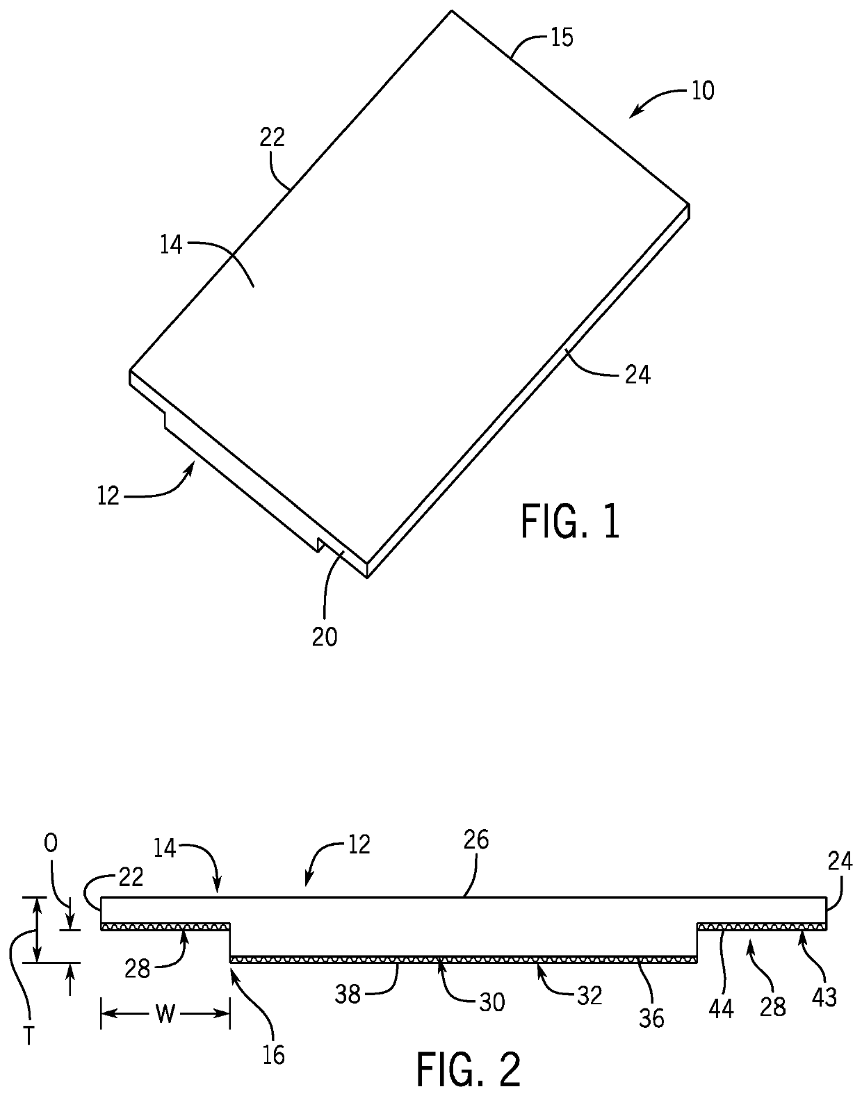
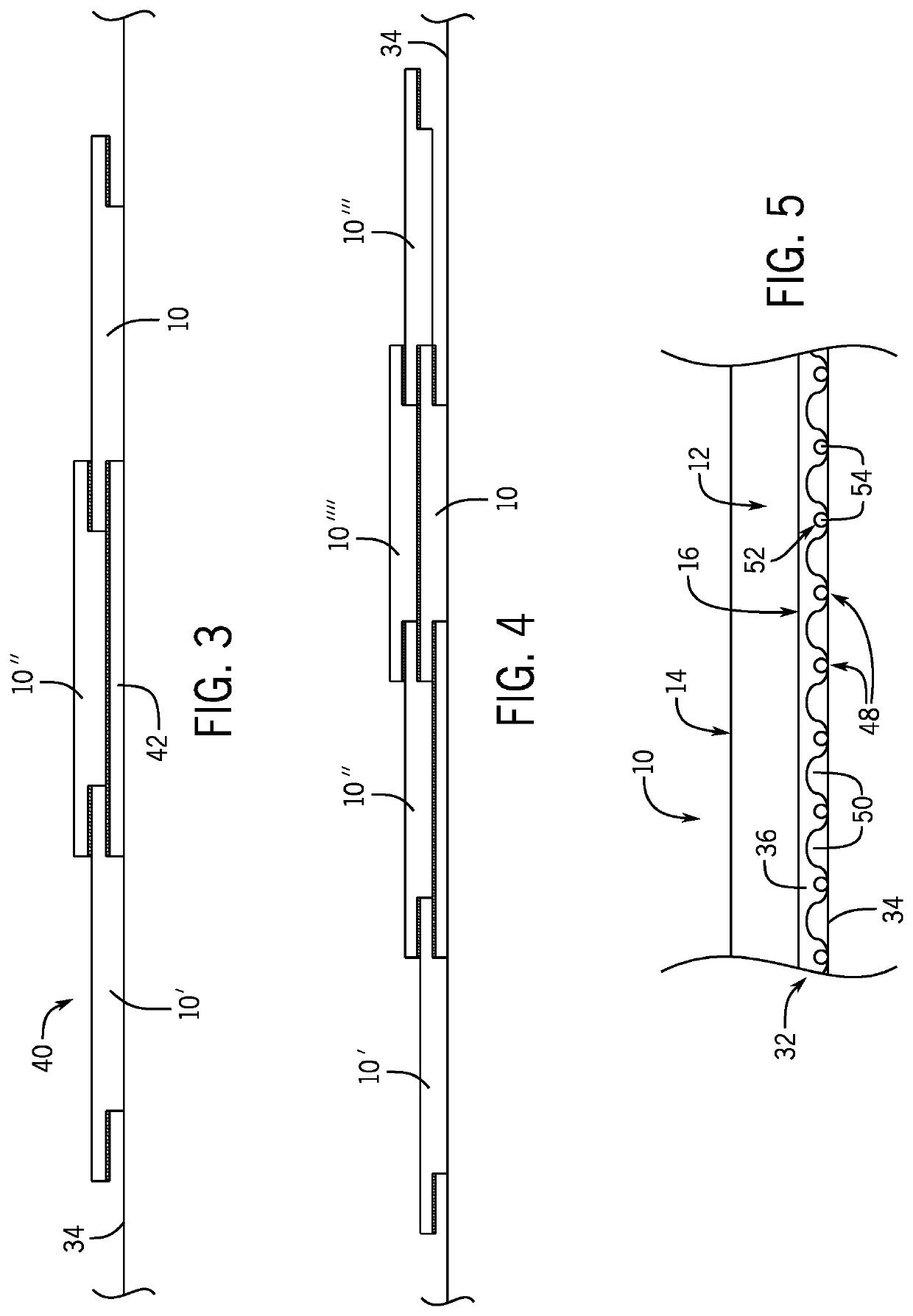
[0036]With reference now to the drawing figures in which like reference numerals designate like parts throughout the disclosure, a wall panel for use in a decorative wall or floor covering system is illustrated generally at 10 in FIG. 1. The wall panel 10 can be formed of any desired material, such as a wood material, a ceramic material a metal material, a laminate material, or any combination thereof. Each panel 10 includes a body 12 having a front surface 14 and a rear surface 16, each of the front surface 14 and the rear surface 16 bounded by a pair of opposed end edges 18,20 and a pair of side edges 22,24.

[0037]Referring now to FIG. 2, in the exemplary embodiment the front surface 14 includes a decorative layer, treatment or other material 26 thereon in order to provide the desired appearance for the wall panel 10. The decorative layer 26 extends over the side edges 22,24 in order to completely cover the exposed areas of the wall panel 10.

[0038]The rear surface 16 of the panel 1...


PUM

PropertyMeasurementUnit
temperatureaaaaaaaaaa
temperature sensitiveaaaaaaaaaa
shapesaaaaaaaaaa

Abstract

A decorative wall system is provided that includes a number of panels that can be secured to an underlying wall and to one another in an overlapping configuration to provide a multi-layer, three-dimensional appearance to the wall. In one embodiment of the wall system, the system includes individual panels that include a decorative front surface and a rear surface. The rear surface includes undercuts along each side of the rear surface that can be positioned over the side edges of the front surface of an adjacent wall panel. The panels may each include an adhesive layer including compressible strings therein that assist the adhesive in holding the panel on a surface by forming a vacuum between the panel and the surface to which the panel is attached.

Description

CROSS-REFERENCE TO RELATED APPLICATIONS[0001]The present application claims priority as a continuation-in-part from U.S. Non-Provisional patent application Ser. No. 17 / 086,657, filed on Nov. 2, 2020, which claims priority as a continuation-in-part from U.S. Reissue patent application Ser. No. 16 / 815,721, filed on Mar. 11, 2020, as well as from U.S. Provisional Patent Application Ser. No. 62 / 944,850, filed on Dec. 6, 2019, U.S. Provisional Patent Application Ser. No. 62 / 934,640, filed on Nov. 13, 2019, and U.S. Provisional Patent Application Ser. No. 62 / 929,510, filed Nov. 1, 2019, each of which are expressly incorporated herein by reference for all purposes.FIELD OF THE INVENTION[0002]The present invention relates to coverings for walls and floors, and more specifically to a system of panels for use as a wall or floor covering.BACKGROUND OF THE INVENTION[0003]In order to cover existing wall structures and floors to provide an aesthetically pleasing appearance, many different types o...

Claims


Application Information

Patent Timeline
Patent Type & Authority Applications(United States)
IPC IPC(8): B32B7/12E04F13/08E04F15/02E04F15/10B32B3/30
CPCB32B7/12E04F13/0866E04F13/0885B32B2607/00E04F15/107B32B3/30B32B2471/00E04F15/0215E04F15/02038E04F15/02155E04F13/0887E04F13/0889B32B21/00B32B2255/26B32B5/02B32B2307/102B32B7/14B32B3/04B32B21/14B32B2255/06B32B3/06B32B2255/08B32B15/00B32B2307/558
Inventor MAGNUSSON, TRYGGVIMAGNUSSON, NATALIE A.
Owner THORHAMMER LLC
Why Eureka
Try Eureka