Furniture drive

a technology for furniture drives and components, applied in the field of furniture drives, can solve the problems of limited adjustment path of the spring device along the threaded spindle, large dimension of the furniture drive, and limited access to the adjustment element, so as to prevent tilting movements or jamming of the components of the furniture drive, and reduce the construction height of the furniture driv

Pending Publication Date: 2022-02-24
JULIUS BLUM GMBH
View PDF0 Cites 3 Cited by
  • Summary
  • Abstract
  • Description
  • Claims
  • Application Information

AI Technical Summary

Benefits of technology

[0010]A further advantage of the present invention is the fact that the arrangement of the adjustment element on the furniture drive is not fixedly predefined. Instead, the adjustment element, in the production of the furniture drive and depending on the type and application field, can be arranged on various desired positions.
[0011]For example, the adjustment element of the adjustment device, in a mounted condition of the furniture drive, faces towards the movable furniture part and is arranged on a front-end region of the carrier. In this way, the accessibility to the adjustment element can be significantly improved. This is also an advantage when the carrier of the furniture drive, in a mounted condition on the furniture panel, is configured to be at least partially, preferably substantially entirely, received within the furniture panel. With a furniture drive integrated within the furniture panel, an accessibility of the adjustment element from the side is only possible through bores of the furniture panel. These bores weaken the furniture panel, are often considered to be visually disturbing and include an additional installation expense. For this reason, an accessibility of the adjustment element from a front-end face of the carrier can really be an advantage.
[0012]The furniture drive can include at least one angularly-movable coupling device for transmitting a rotational movement of the adjustment element into a rotational movement of the threaded section. For realizing an angularly-movable coupling device, which provides a transmission of torque in a flexed shaft train, various possibilities are available for the person skilled in the art. The angularly-movable coupling device can include at least one elastic element, preferably a folding bellows, a rubber form element or a coil-spring coupling, and / or at least one gear, preferably a bevel gear transmission, and / or a joint, preferably a cross-joint or a cardan joint.
[0013]The furniture drive can include at least one shaft configured to be driven by the adjustment element, the at least one shaft being provided for driving the threaded section. The at least one shaft can be displaceably supported relative to the carrier in or along a guide, preferably an elongated hole. In this way, compensation movements of components of the furniture drive caused by the angularly-movable coupling device can be at least partially compensated for, in order to prevent tilting movements or jamming of the components of the furniture drive.
[0014]The adjustment element of the adjustment device can include a receiving device for a tool, preferably a screwdriver. The adjustment element can be driven by exerting a torque to the receiving device with the aid of the tool. For example, the receiving device can include a cross-head form (for example a Pozidriv-profile), a square profile, a hexagonal profile or a six-lobe drive (for example a Torx-profile).
[0015]The carrier of the furniture drive can be configured as a mounting plate or as a, in particular cuboidal, housing. The carrier can have a substantially rectangular form, and it can be preferably provided that the ratio of a length of the carrier relative to a height of the carrier is larger than 1 to 0,7, preferably larger than 1 to 0,5. By such a dimensioning of the carrier, a reduced constructional height of the furniture drive can be provided.

Problems solved by technology

A drawback of the known furniture drives is the fact that the construction of the furniture drive, due to the position of the spring assembly to be adjusted, has to be dimensioned relatively large.
Moreover, the adjustment path of the spring device along the threaded spindle is limited.

Method used


Image

  • Furniture drive
  • Furniture drive
  • Furniture drive

Examples


Embodiment Construction

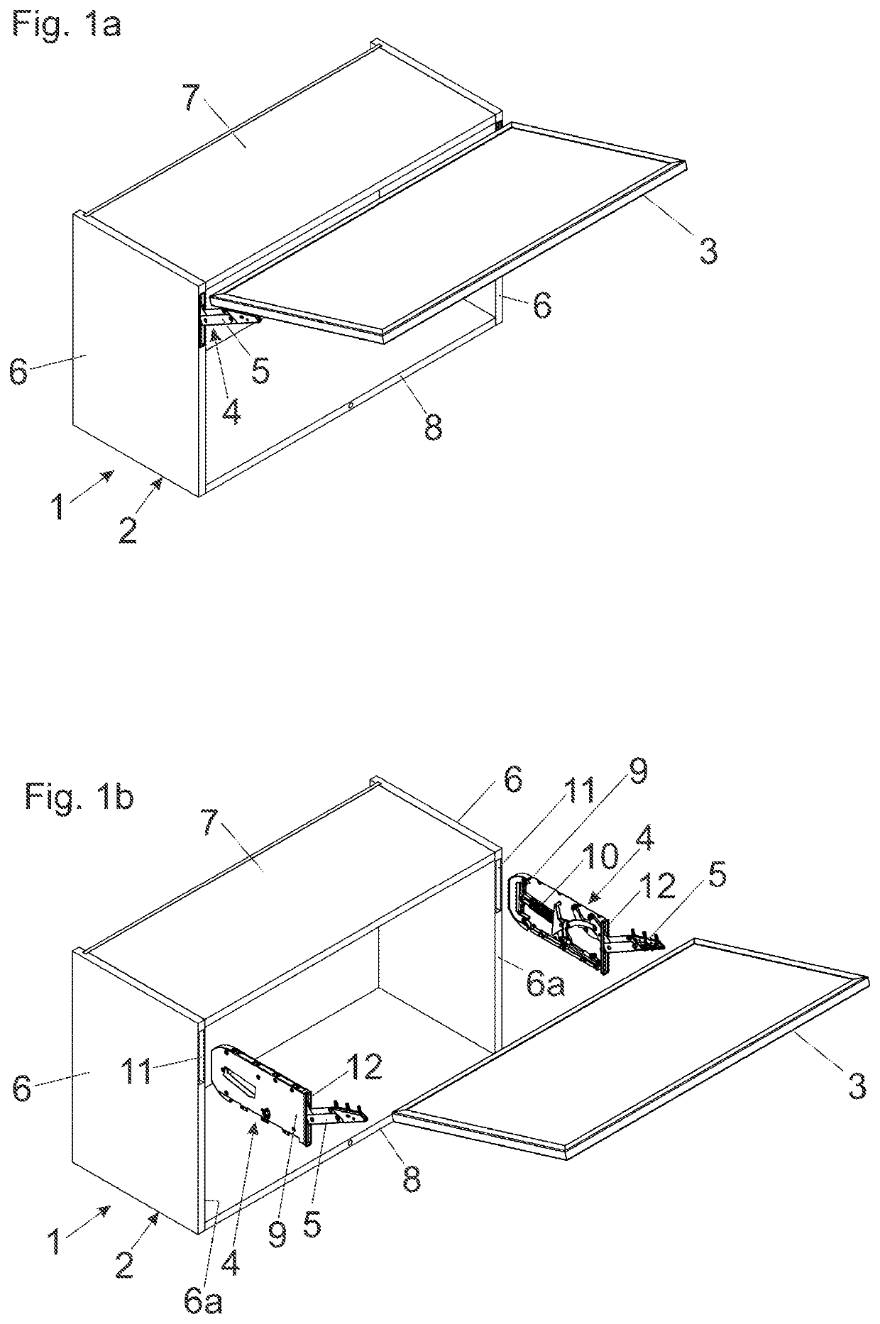
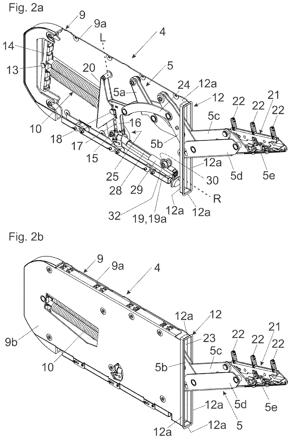
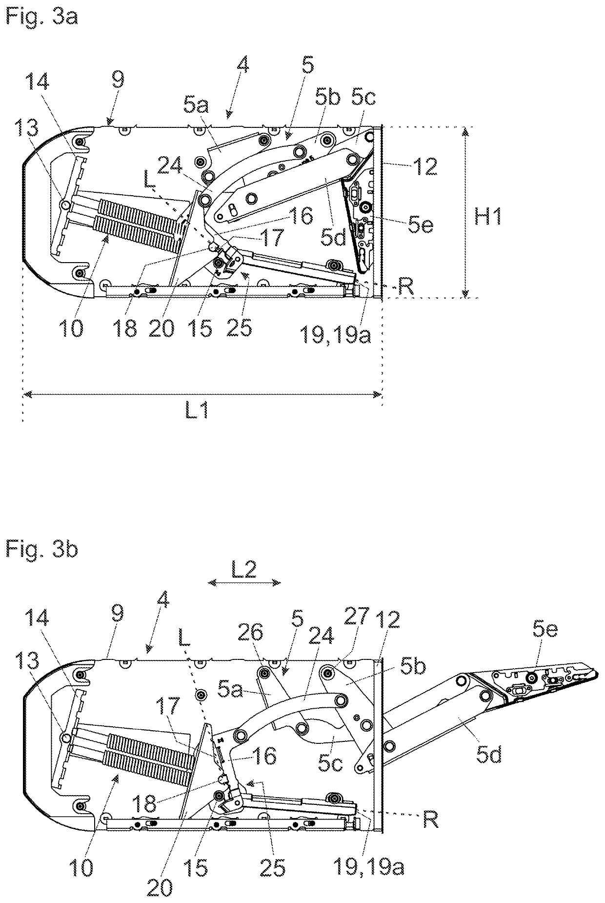
[0024]FIG. 1a shows a perspective view of an item of furniture 1 comprising a furniture carcass 2, a furniture part 3 movably-supported relative to the furniture carcass 2, and at least one furniture drive 4 for moving the movable furniture part 3. The item of furniture 1 includes furniture panels 6 in the form of sidewalls, a top panel 7 and a bottom panel 8. In the shown embodiment, the furniture drive 4 is at least partially, preferably substantially entirely, integrated into the sidewall configured as a furniture panel 6. The movable furniture part 3 is movably supported between a closed position in which the furniture carcass 2 is covered, and an elevated open position in relation to the furniture carcass 2. Of course, it is also possible to integrate the furniture drive 4 into a horizontally extending furniture panel, such as, for example, into the top panel 7, into the bottom panel 8 and / or into a shelf arranged between the top panel 7 and the bottom panel 8. In such a case, ...


PUM


Abstract

A furniture drive includes a carrier configured to be fixed to or within a furniture panel of a furniture carcass, an actuating arm assembly arranged on the carrier, a spring device for applying a force to the actuating arm assembly, an adjustment device for adjusting a force of the spring device to the actuating arm assembly, and a threaded section having a longitudinal direction. An engagement location of the spring device is adjustable along the threaded section by a rotation of an adjustment element about a rotational axis, and the rotational axis of the adjustment element and the longitudinal direction of the threaded section enclose an angle to one another. The angle formed by the rotational axis of the adjustment element and the longitudinal direction of the threaded section is configured to be varied upon a movement of the actuating arm.

Description

BACKGROUND OF THE INVENTION[0001]The present invention relates to a furniture drive for moving a furniture part movably-supported relative to a furniture carcass. The furniture drive includes a carrier configured to be fixed to or within a furniture panel of the furniture carcass, and an actuating arm assembly arranged on the carrier, in which the actuating arm assembly includes at least one movably-supported actuating arm for moving the movable furniture part. A spring device is provided for applying a force to the actuating arm assembly, and an adjustment device is provided for adjusting a force of the spring device to the actuating arm assembly. The adjustment device includes an adjustment element rotatable about a rotational axis, and a threaded section having a longitudinal direction. An engagement location of the spring device is adjustable along the threaded section by a rotation of the adjustment element about the rotational axis, and the rotational axis of the adjustment el...

Claims


Application Information

Patent Timeline
Patent Type & Authority Applications(United States)
IPC IPC(8): E05F1/10E05F3/22E05F1/12E05F1/14
CPCE05F1/1058E05F3/22E05F1/1261E05Y2600/452E05Y2900/20E05Y2600/41E05F1/14E05D15/40E05D15/401E05F1/1041E05F1/105E05Y2201/25E05Y2600/20E05Y2201/492E05Y2201/696
Inventor HOLZAPFEL, ANDREAS
Owner JULIUS BLUM GMBH
Why Eureka
Try Eureka