Self-locking pin

Active Publication Date: 2022-02-24
PIVOT POINT
View PDF6 Cites 0 Cited by
  • Summary
  • Abstract
  • Description
  • Claims
  • Application Information

AI Technical Summary

Benefits of technology

The present invention is a self-locking pin with a single piece construction plunger. This design makes it easy to install the pin through an aperture in an object and reduces costs associated with the pin. The plunger has a section that pushes the pin into position and a biasing section that ensures the pin stays in place. This design allows for easy and cost-effective installation of the self-locking pin.

Problems solved by technology

However, these dual fasteners make safety bolts more difficult and thus more expensive to manufacture.
Additionally there are some applications where such a bolt cannot be used because it is either impractical or impossible to access the threaded end of the bolt after it is inserted through an aperture.
Also, screwing the nut on the end of the bolt causes an increase in assembly Lime.

Method used


Image

  • Self-locking pin
  • Self-locking pin
  • Self-locking pin

Examples


Embodiment Construction

[0042]Although the disclosure hereof is detailed and exact to enable those skilled in the art to practice the invention, the physical embodiments herein disclosed merely exemplify the invention which may be embodied in other specific structures. While the preferred embodiment has been described, the details may be changed without departing from the invention, which is defined by the claims.

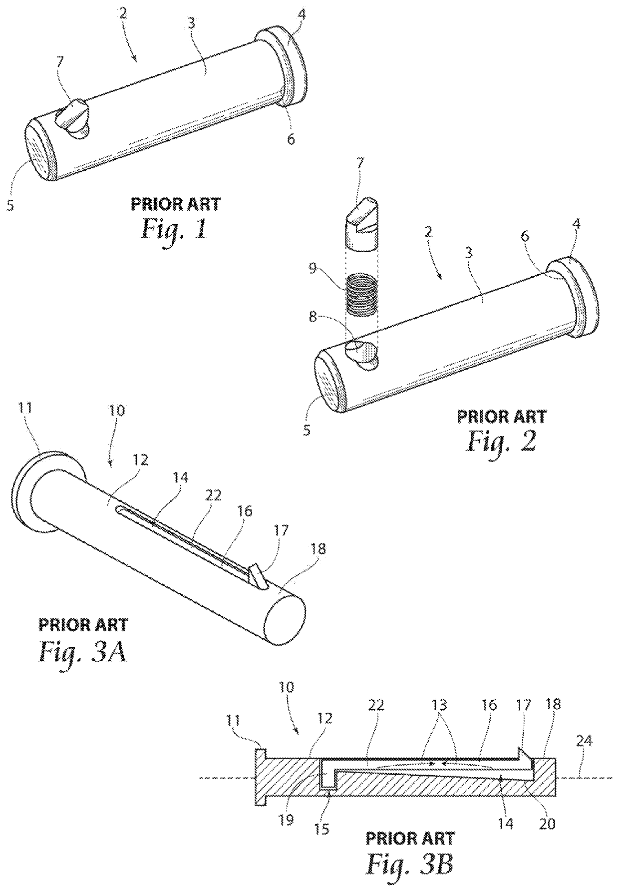
[0043]With reference to FIGS. 1 and 2, a first prior art pin 2 is illustrated. The first prior art pin 2 comprises a cylindrical shaft 3 having a first end 5 and a second end 6. A head 4 is positioned at the second end 6.

[0044]As illustrated in FIG. 2, a bore 8 extends partway through the shaft 3 in close proximity to the first end 5. A plunger 7 is slidably disposed in the bore 8. The plunger 7 sits on a coil spring 9, where the plunger 7 and the coil spring 9 are two separate components of the pin 2.

[0045]With reference to FIGS. 3A and 3B, a second prior art pin 10 is illustrated. The second pri...


PUM


Abstract

A self-locking pin having a shaft, a headed end, and plunger biased in a bore in the pin. The portion of the detent or plunger that extends outwardly from the bore may be wedge-shaped, or possess other geometrical shapes, while the portion of the plunger disposed inside the bore is of a cylindrical shape or other geometrical shapes. The plunger comprises a plunger section and a biasing section in a unitary one-piece construction. At least one transition ledge is defined on the plunger. The shaft is staked at points along the perimeter of the bore so that the inwardly extending surface created by the staking abuts the transition ledge and prevents the plunger from rotating or being removed from the bore.

Description

BACKGROUND OF THE INVENTION[0001]The invention relates to fasteners, namely threadless fasteners and more particularly to a threadless fastener for retaining two or more structures through apertures formed in each structure.[0002]Detent pins are well known in industry. Many of these pins fall into the category of safety bolts. Safety bolts have a threaded end to which a nut can be attached to as well as a detent mechanism along the length of the bolt. The main fastening mechanism in safety bolts is threading the nut on the end of the bolt. These products are often used in the aircraft industry so an extra safety factor is present in case vibrations cause the nut to loosen or someone forgets to tighten the nut. The detent mechanism is this extra safety factor. However, these dual fasteners make safety bolts more difficult and thus more expensive to manufacture. Additionally there are some applications where such a bolt cannot be used because it is either impractical or impossible to ...

Claims


Application Information

Patent Timeline
IPC IPC(8): F16B21/12F16B19/10
CPCF16B21/125F16B19/109F16B7/105
Inventor BAUS, ROMAN J.
Owner PIVOT POINT
Why Eureka
Try Eureka