Pipe connector

Active Publication Date: 2022-02-24
KENNEDY VALVE
View PDF0 Cites 1 Cited by
  • Summary
  • Abstract
  • Description
  • Claims
  • Application Information

AI Technical Summary

Benefits of technology

[0006]A pipe connector to connect to an end of a pipe or pipe fitting provides a single

Problems solved by technology

The retention mechanism and the sealing mechanism often have separate structural or functional aspects requiring separate implementation, or producing insufficient levels of retention or sealing.
This solution requires both threading the pipe and rotating the pipe or the body to seat the connection, a requirement that can be a pro

Method used


Image

  • Pipe connector
  • Pipe connector
  • Pipe connector

Examples


Example

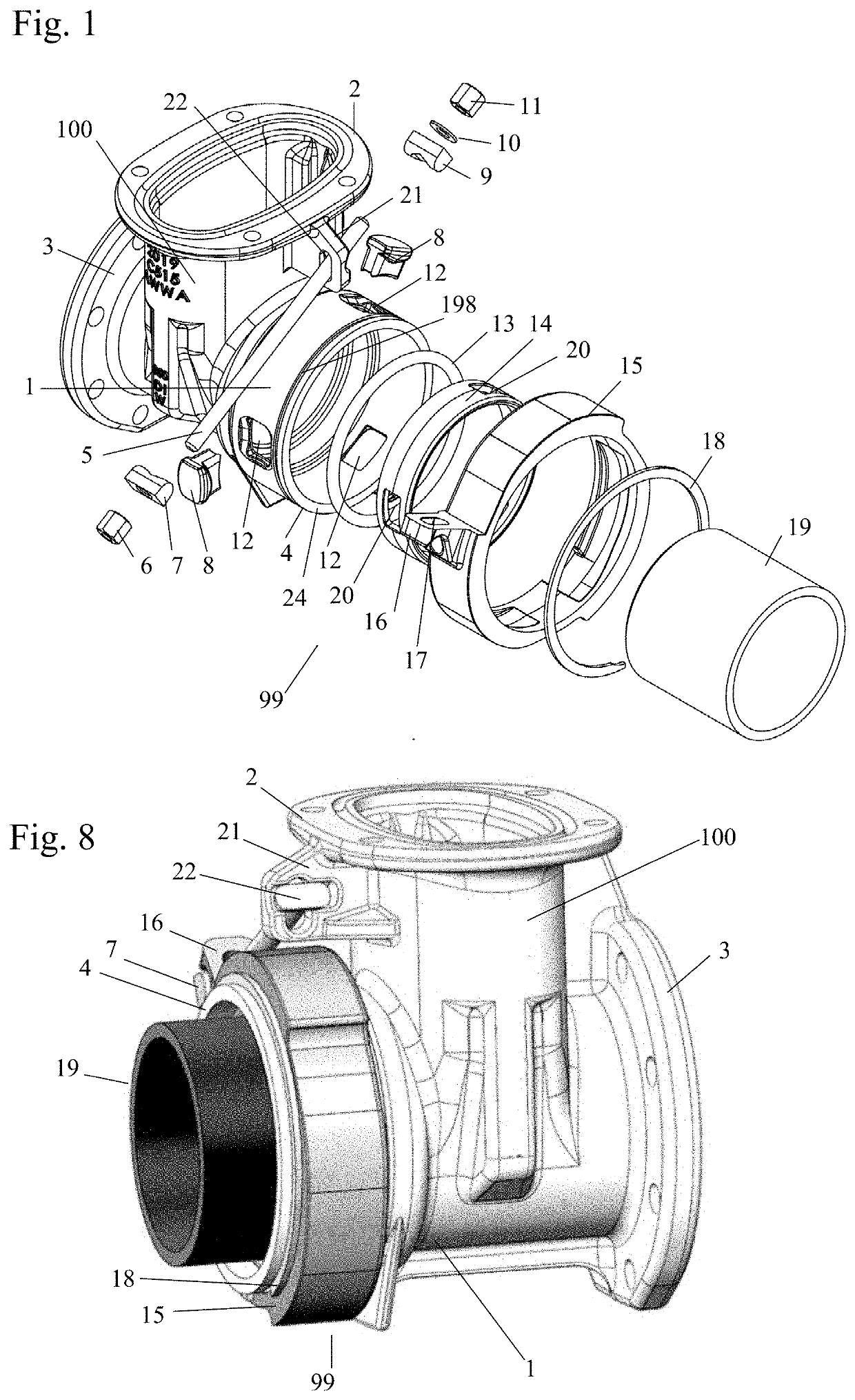
[0038]FIG. 1 shows an exploded view of a valve 100 including a pipe connector 99, according to an embodiment of the invention, while FIG. 8 shows a perspective view of the valve 100 and the pipe connector 99 with a pipe 19 inserted into the pipe connector 99. The pipe connector 99, while shown integrated as part of the valve 100, can be implemented as part of a variety of valves, adapters, couplings, or other piping or plumbing fittings and applications. Accordingly, the operational components of the valve 100, which are not relevant to the inventive pipe connector 99, are omitted from the drawings and the following description.

Components of the Pipe Connector

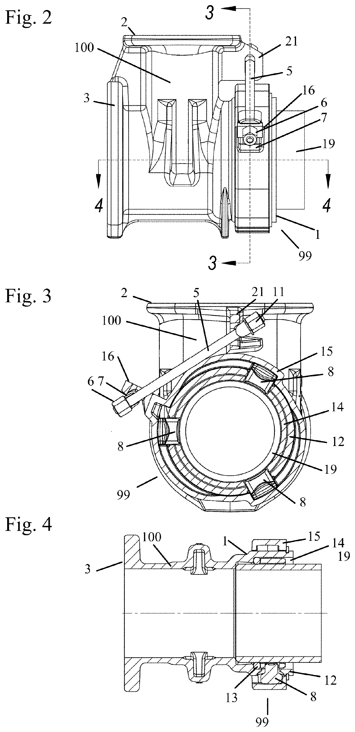
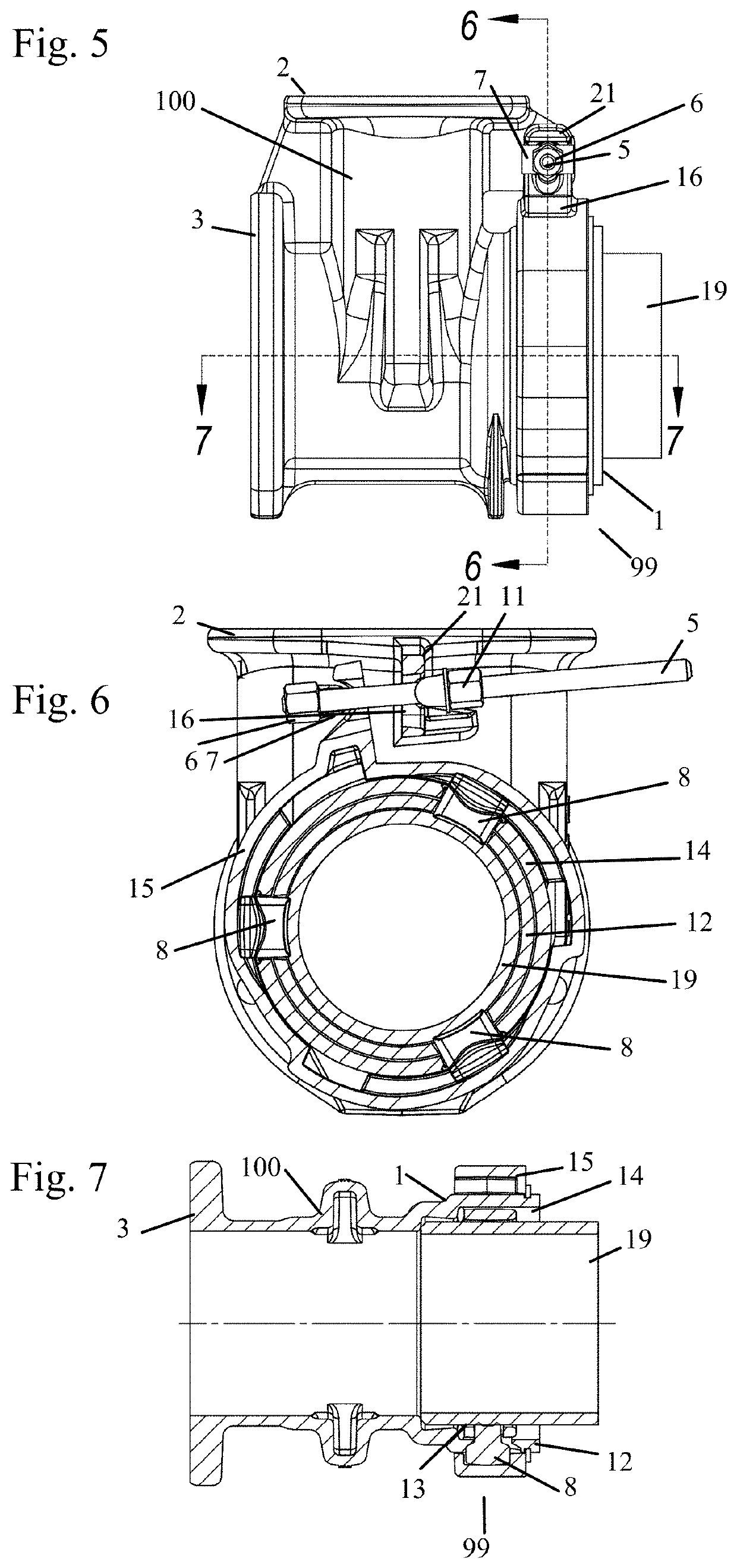
[0039]Referring to FIGS. 1-16b, the pipe connector 99 provides a fluid seal and mechanical connection between a body 1 of the pipe connector 99 and a pipe or conduit 19. The body 1 is integrated with the valve 100 as shown herein, but may also be integrated with some other sort of device as noted above.

[0040]FIG. 9 shows a pers...


PUM


Abstract

A pipe connector includes a body, a cam ring, a seal element, a push ring, and a gripper. The body has an aperture through an outer surface. The cam ring is configured to be located around the outer surface. The seal element is configured to be seated around an inner surface of the body. The push ring is configured to be slideably located within the body, and to have an aperture configured to be aligned with the aperture of the body. The gripper is configured to be located through the aperture in the body and into a first depth of the cam element. The cam ring is configured to rotate, moving the gripper axially to draw the push ring against the seal element and to move the gripper radially to grip the pipe.

Description

BACKGROUND OF THE INVENTIONField of the Invention[0001]The invention pertains to the field of pipe connectors. More particularly, the invention pertains to a pipe connector and a method to connect pipes.Description of Related Art[0002]The installation of some pipe connectors requires insertion of an end of a pipe into a body of the pipe connector. To avoid decoupling of the pipe from the pipe connector, some sort of retention mechanism physically holds the pipe end in the body, and to avoid leaks, some sort of sealing mechanism creates a fluid-tight seal between the pipe and the body. The retention mechanism and the sealing mechanism often have separate structural or functional aspects requiring separate implementation, or producing insufficient levels of retention or sealing.[0003]One retention and sealing mechanism includes threading the end of the pipe into a threaded portion of the body. This solution requires both threading the pipe and rotating the pipe or the body to seat the...

Claims


Application Information

Patent Timeline
IPC IPC(8): F16L21/08F16L27/113
CPCF16L21/08F16L27/113
Inventor KENNEDY, PAUL
Owner KENNEDY VALVE
Why Eureka
Try Eureka