Steerable instrument comprising a detachable part

Pending Publication Date: 2022-03-03
FORTIMEDIX ASSETS II BV
View PDF0 Cites 2 Cited by
  • Summary
  • Abstract
  • Description
  • Claims
  • Application Information

AI Technical Summary

Benefits of technology

[0030]According to an embodiment, the support part and/or the elongate instrument comprise a coupling part for coupling to a steering device. This can be in the shaft and/or elongated elements, for example, coupling parts on the ends of elongated elements and/or portions of fingers can secure to parts of the steering device. In some embodiments, the elongated elements and/or fingers connect to a steering plate, and the shaft connects to the steering device as well. The steering device can then move the elongated elements longitudinally with respect to the shaft thereby

Problems solved by technology

Most of the known instruments are complex to manufacture resulting in expensive instruments.
However, most plastics are rather weak.
In case of very long instruments, e.g. longer than 1 meter, problems may arise due to the high forces exerted on the cables, both the steering cables and the actuation cable arranged to operate the tool at the distal end of the instrument.
Problems may be undesired cuts, slip stick effects in the plastic tube and often too high friction on the cables causing steering by the steering cables to be difficult and hard to manage.
Moreover, mechanical properties of many plastics may be too poor to guarantee a high enough torsional stiffness which is required because the instruments should be capable of being rotated in use where they may have been guided through several curves impeding rotation of the whole instrument.
Another disadvantage of a plastic tube may be that in case it is provided with an actuation cable to operate a tool at the distal end of the instrument the force in the actuation cable can increase to an extent that it exceeds the maximum longitudinal force allowed in the extruded plastic tube.
If so, it would be impossible to operate the tool wit

Method used


Image

  • Steerable instrument comprising a detachable part
  • Steerable instrument comprising a detachable part
  • Steerable instrument comprising a detachable part

Examples


second embodiment

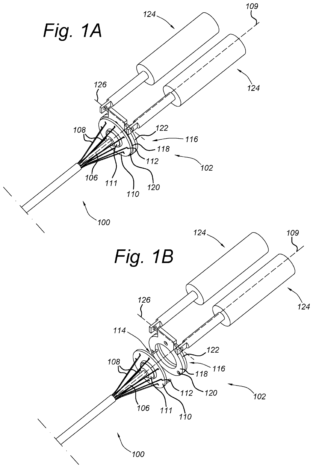
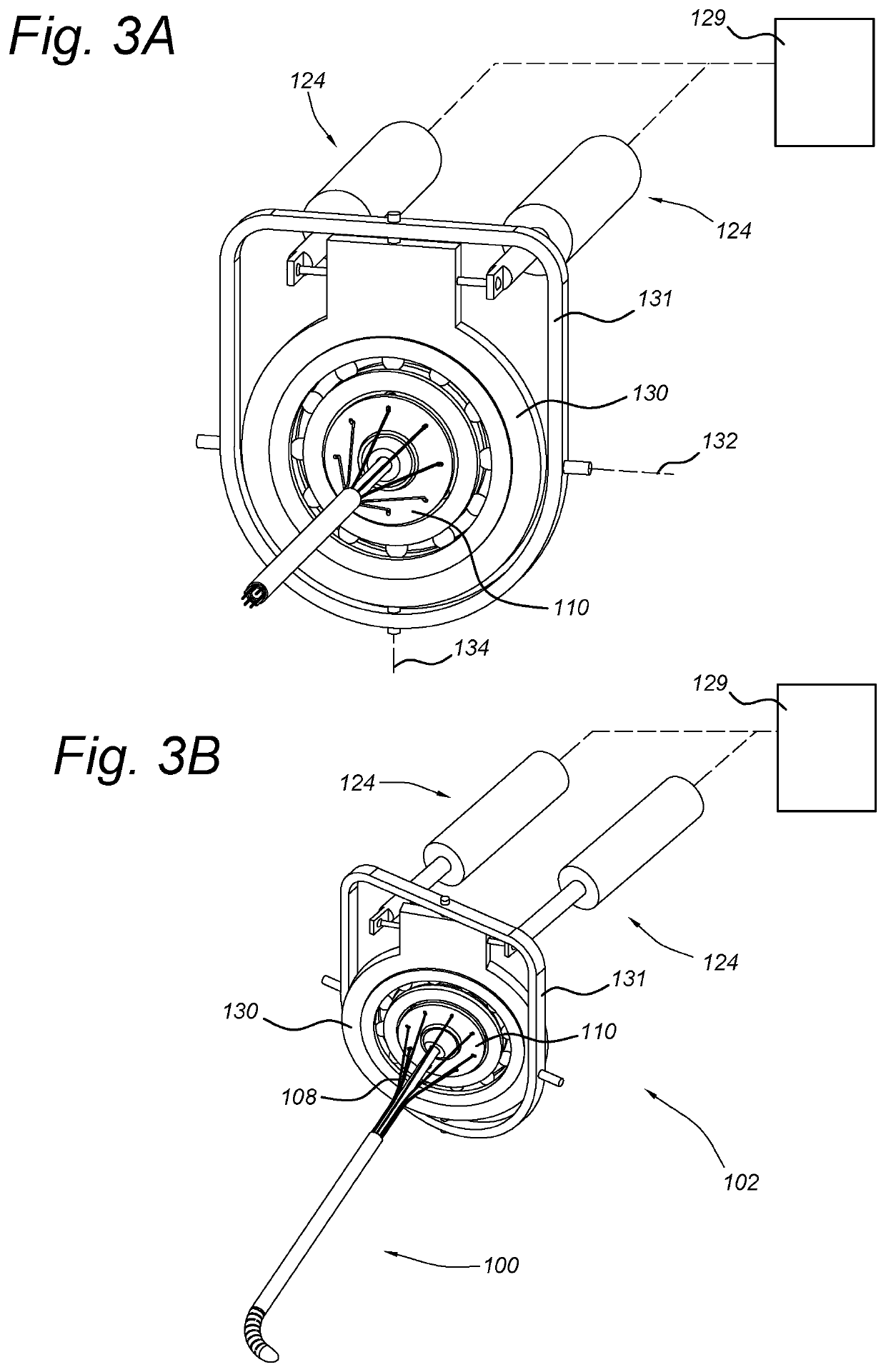
[0061]FIG. 3A shows a perspective view of an end of an instrument 100 connected to a steering device 102 which includes a schematic depiction of robotic control 129, and FIG. 3B shows the full instrument 100 with steering device 102, connected and with a deflection of the distal end. Instrument 100 is coupled to steering device 102 as in FIGS. 1A-2B, with steering plate 110 coupled to a locking plate of steering device 102 (not shown in FIGS. 3A-3B).

[0062]Steering device 102 includes inner frame 130 connected to outer frame 131 at hinge axis 134 such that inner frame 130 can rotate within outer frame 131 about axes 134. The rotation about axis 134 is controlled by actuators 124. Outer frame 131 is connected to steering device 102 at hinge axis 132 (such a connection is not shown in FIGS. 3A, 3B). The rotation about axis 132 is also controlled by actuators 124. Such a suspension about two axes 132 and 134 allows movement of steering plate 110 at any angular position in space. Steerin...

third embodiment

[0092]FIG. 13 shows a perspective view of a support part 1320, also formed from an outer longitudinal tube 1322 which is cut longitudinally to form fingers 1324. Fingers 1324 include an opening 1326 to which elongated elements 1102 can connect. Elongated elements 1102 in the form of flexible cables connect to openings 1326 through a hook connection which secures the cables with respect to a finger 1324. Other suitable connections can include connecting through another element, laser welding, brazing and / or bonding. In this embodiment, fingers 1324 then include a connection portion 1328 which can connect to a steering plate and / or steering device.

[0093]The longitudinal cuts of tube 1322 may extend only part or the whole length of the instrument, and in some embodiments can be used for transmitting steering or bending forces from a proximal end to the distal end.

[0094]The support part fingers shown in FIGS. 11-13 can be made in the configuration shown, and when the instrument is packa...


PUM


Abstract

A steering device for connecting to an elongated instrument comprises a locking plate with a coupling to which a steering plate of the instrument can secure such that the steering plate and the locking plate move together; and a steering unit for moving the locking plate. The elongated instrument comprises a plurality of elongated elements extending along an instrument shaft and secured to a steering plate at a proximal end of the instrument shaft, with the steering plate being movably connected around a support member secured to the shaft.

Description

FIELD OF THE INVENTION[0001]The present invention relates to a steerable instrument for invasive and non-invasive type of applications, such as in surgery. Such instruments can be used in, for instance, the field of gastroscopy, colonoscopy, endoscopy, laparoscopy, and other medical applications. However, the steerable instrument according to the invention can also be used in non-medical applications. Examples of the latter include inspection and / or repair of mechanical and / or electronic hardware at locations that are difficult to reach.BACKGROUND ART[0002]Transformation of surgical interventions that require large incisions for exposing a target area into minimal invasive surgical interventions, i.e. requiring only natural orifices or small incisions for establishing access to the target area, is a well-known and ongoing process. In performing minimal invasive surgical interventions, an operator such as a physician, requires an access device that is arranged for introducing and gui...

Claims


Application Information

Patent Timeline
IPC IPC(8): A61B1/005A61B17/00
CPCA61B1/0057A61B34/30A61B17/00234A61B1/0052A61B34/71A61B2034/301A61B2017/00323
Inventor THISSEN, MATTHEUS HENDRIK LOUISVERBEEK, MARCEL ANTONIUS ELISABETH
Owner FORTIMEDIX ASSETS II BV
Why Eureka
Try Eureka