forceps

Active Publication Date: 2016-09-08
KARL KLAPPENECKER
View PDF3 Cites 0 Cited by
  • Summary
  • Abstract
  • Description
  • Claims
  • Application Information

AI Technical Summary

Benefits of technology

[0036]Since all of the connections of the forceps are designed to be releasable or plugged-in, the individual parts of the forceps can readily also be cleaned individually. It is also easily possible to interchange individual parts. This has the advantage that, in the event of a defect of an ind

Problems solved by technology

It is disadvantageous, however, that the cutting edges in the open state spread far apart from each other and are not aligned parallel to each other, and therefore there is the possibility that the wire may slide out of the cutting edges when the forceps are pressed together.
In general, the cleaning of the complex devices constitutes a growing problem recently in the sphere o

Method used


Image

  • forceps
  • forceps
  • forceps

Examples


Embodiment Construction

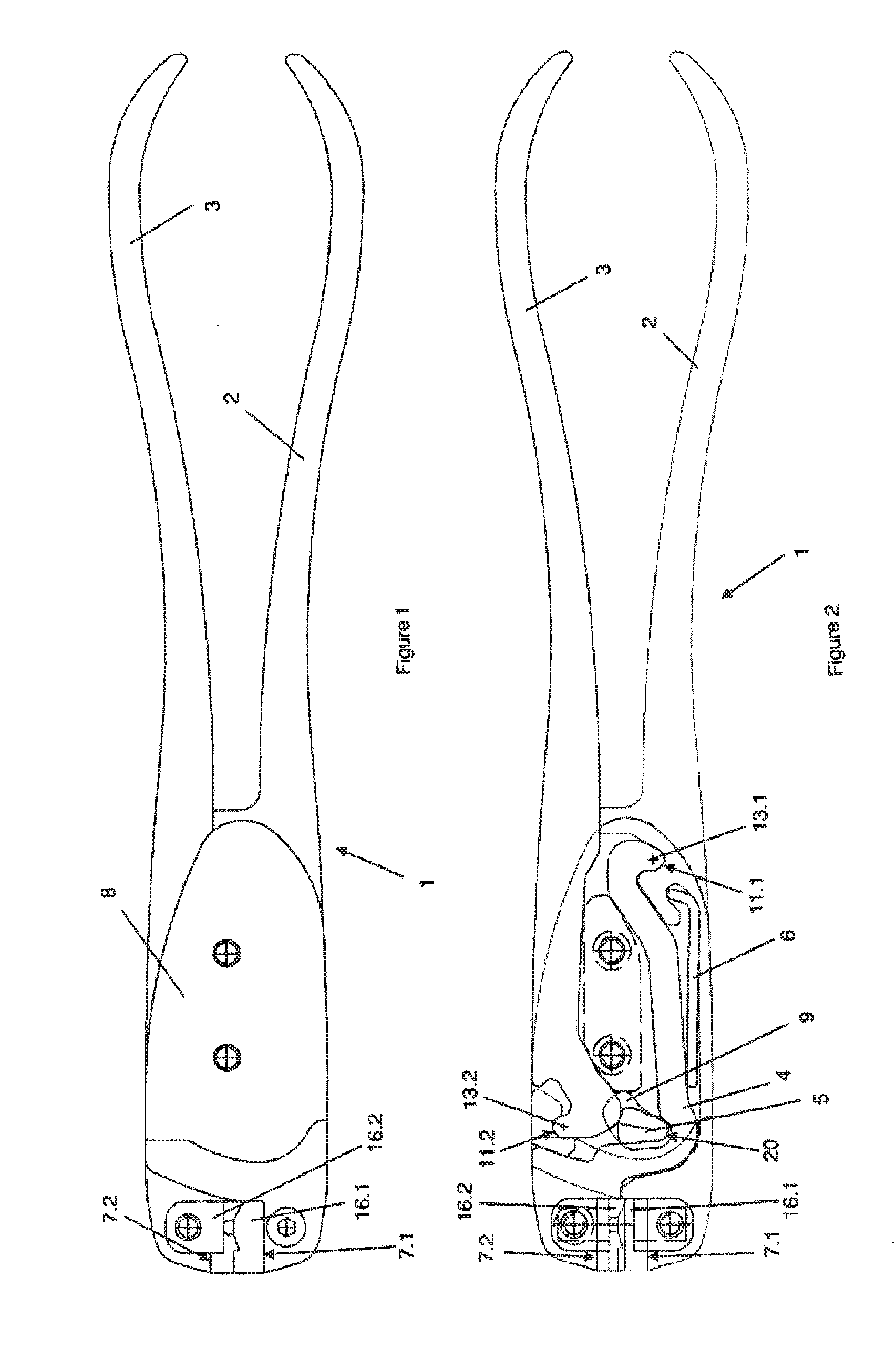
[0057]FIG. 1 shows a typical embodiment of a forceps 1 according to the invention with a closed jaw. A forceps according to the invention comprises here a pressure lever 3 next to a handle part 2 with a jaw part 7.1. Said pressure lever 3 is mounted pivotably in relation to the handle part 2.

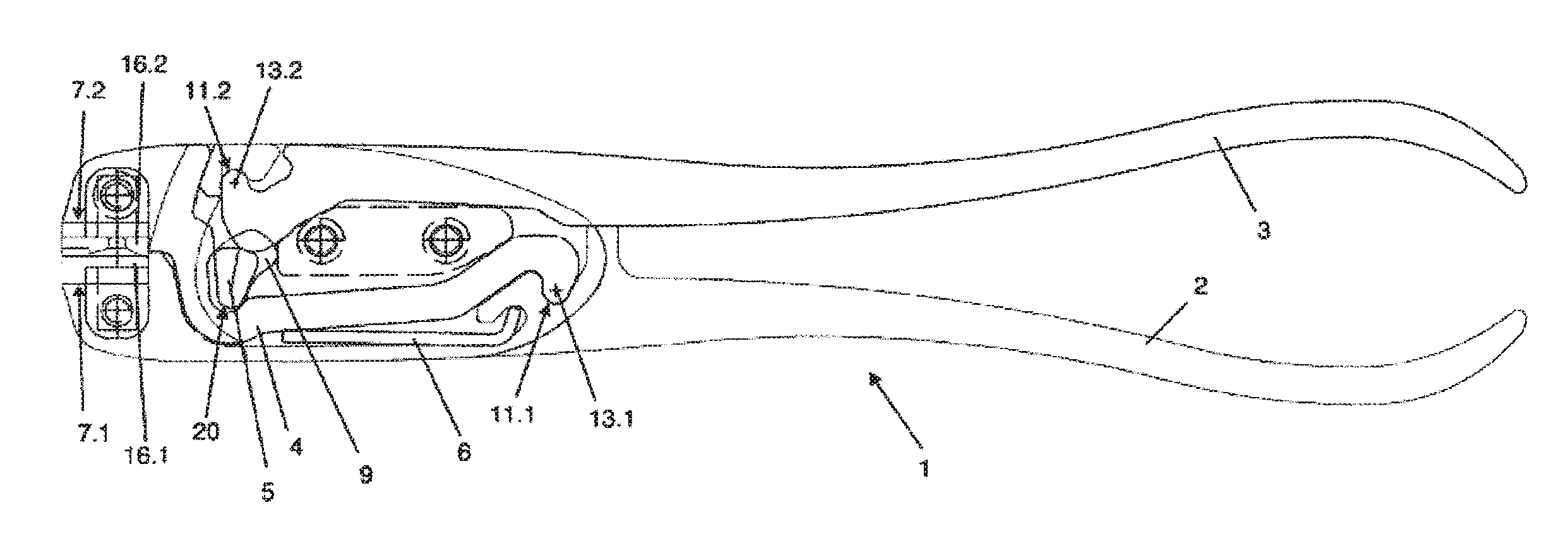
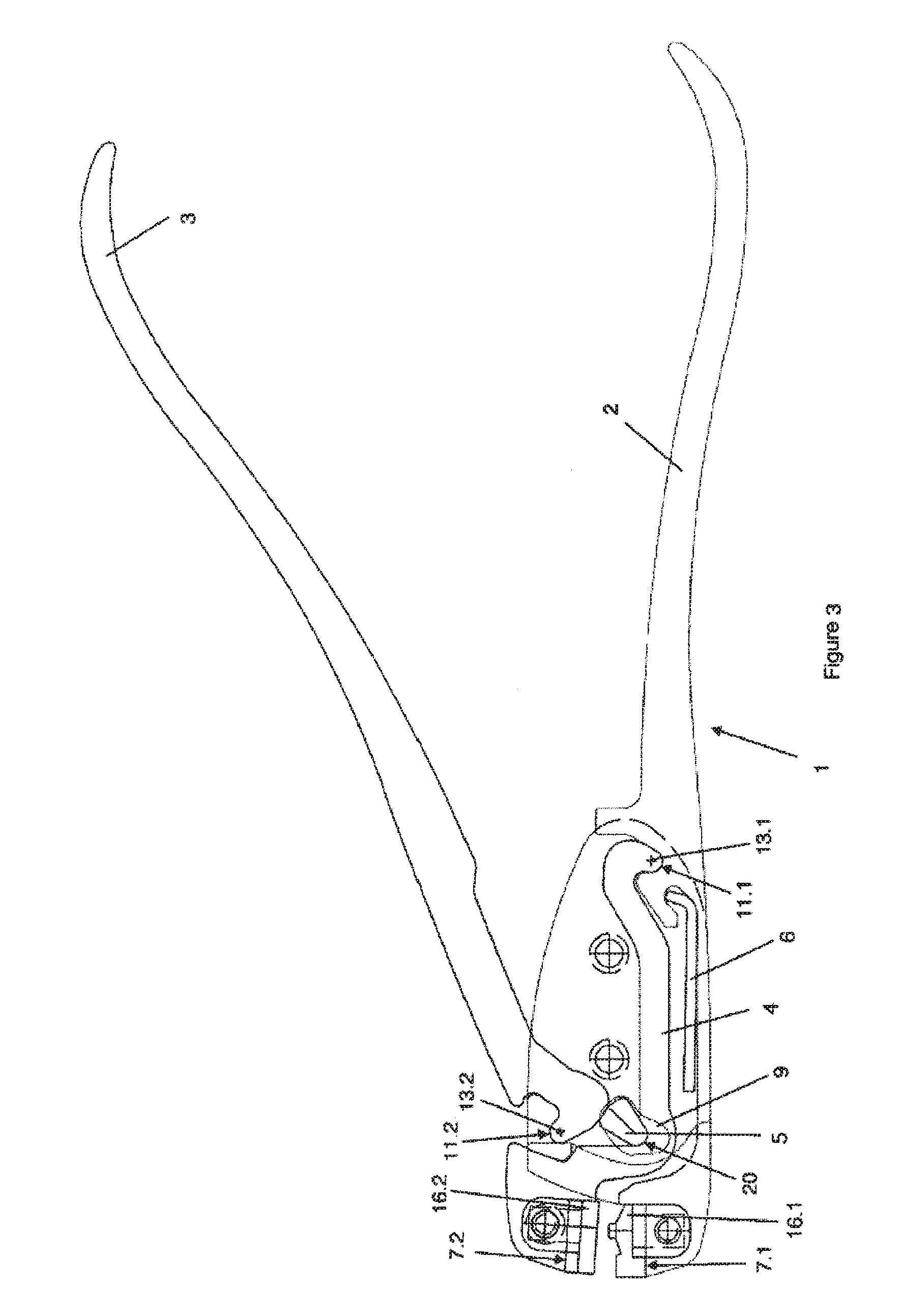
[0058]FIG. 2 shows the forceps 1 according to FIGS. 1 without a housing cover 8. A fulcrum / pivot point 13.2 about which the pressure lever 3, in a typical exemplary embodiment, turns or pivots is illustrated there. Said fulcrum / pivot point is located on that side of the pressure lever 3 which faces the jaw parts 7.1 and 7.2.

[0059]Furthermore, a forceps according to the invention comprises a lever arm 4 with a second jaw part 7.2. In a typical exemplary embodiment, said jaw part is arranged between the handle part 2 and the pressure lever 3 and can be pressurized by the pressure lever 3.

[0060]In FIG. 2, said lever arm 4 is illustrated in a state used in the forceps 1. It is furthermore shown that...


PUM


Abstract

A forceps, in particular surgical forceps, having at least one handle and a pressure lever which is mounted in a pivotal manner relative to the handle and further having a jaw consisting of two jaw parts, one of which is provided on the handle. A lever arm is to be arranged between the handle and the pressure lever, wherein the lever arm has the second jaw part and pressure can be applied to the lever arm by the pressure lever.

Description

BACKGROUND OF THE INVENTION[0001]The invention relates to a forceps, in particular a surgical forceps.[0002]Various surgical forceps for cutting implants and / or medical wires are known from the prior art. Since frequently high shearing forces have to be produced in order to cut implants and / or medical wires, said forceps generally have multiple transmission ratios, for example in the form of toggle lever drives. Furthermore, said forceps are generally shaped ergonomically in order to be able to be operated by the operator using one hand.[0003]EP 0 321 884 B1 depicts a forceps for cutting wire, which is provided with a plurality of toggle lever drives connected via bolts. Said toggle lever drives are intended to permit cutting even of thicker wires using one hand. It is disadvantageous, however, that the cutting edges in the open state spread far apart from each other and are not aligned parallel to each other, and therefore there is the possibility that the wire may slide out of the...

Claims


Application Information

Patent Timeline
IPC IPC(8): B26B13/04B26B29/00B23D29/02
CPCB26B13/04A61B2017/00526B26B29/00B23D29/023A61B17/8863B26B13/28
Inventor SPITZNAGEL, BERNHARD
Owner KARL KLAPPENECKER
Why Eureka
Try Eureka