Embedded metal reinforced structural element and methods for design and manufacture

a technology of embedded metal and structural elements, applied in the field of structural materials, can solve the problems of insufficient disclosure of non-metallic reinforcement properties of the prior art, insufficient evaluation of variability effects, and insufficient disclosure of information to permit computer modeling of stresses and deflection of beams, etc., to achieve the effect of improving plurality of properties and diffusing modulus of elasticity

Undetermined Publication Date: 2007-01-25
BOLAND JAMES
View PDF0 Cites 2 Cited by
  • Summary
  • Abstract
  • Description
  • Claims
  • Application Information

AI Technical Summary

Benefits of technology

[0050] (k) Providing a method for designing and manufacturing T-elements to take advantage of differing modulus of elasticity in tension or compression, or differing strength properties in tension, compression, or bending that are common in composite materials.
[0051] Accordingly, the reader will see that the teachings of this invention will enable many segments of the Forest Products Industry to supply improved products that are more environmentally friendly than those commercially available today.
[0052] The present invention relates to embedded-metal-reinforced-wood structural elements (EMRSE). Such EMRSE may contain one or more elongated non-metallic composite materials and one or more piece of embedded metal assembled to form a composite structural element. These EMRSE may be used in the building of structures such as homes, bridges, towers, warehouses, other dwellings and buildings where sawn timbers have historically been used. The embedded metal may be fixed firmly between two or more surfaces of non-metallic composite material and adhesively bonded to the metal in a manner that enables forces to be transmitted between materials. The metal reinforced structural element forms a basic building block that may used to form structural elements of any size, shape, or configuration. Such structural elements may include trusses, metal plate connected trusses, beams, I-beams, T-beams, box beams, columns, joists, and the like. The embedded metal reinforcements may be provided in the web or core of the element to resist shear stresses or secondary stresses.
[0053] In one configuration the EMRSE may be an elongated wood member with at least one metal piece fully embedded in the member and approximately flush with a surface of the wood structural element. The metal piece is adhesively bonded to the wood structural element. The resulting composite structural element has at least one property improved by at least a predetermined amount compared to the unreinforced structural element. The EMRSE may also contain a plurality of metal pieces that are so arranged and sized whereby the resulting composite structural element has a plurality of properties improved compared to said unreinforced structural element.
[0054] Alternatively, the EMRSE may have a first elongated wood member with one or more pieces of metal partially embedded in a groove in the wood member. A second elongated wood member also with a groove. The two wood members may be joined by adhesively binding the partially embedded metal piece in the groove of the second wood member. Such joint may be described as a tongue and grove joint. This application creates a means for joining structural elements to construct composite reinforced structural elements of various shapes and properties. This approach may be repeated to join multiple structural elements in near infinite variety of shapes and sizes. The invention also relates to structural elements where in the structural element is constructed from a plurality of pieces laminated together (a glue laminated structural element).
[0055] The metal used in reinforcing the wood structural elements may be selected from a wide variety of metals. Generally, cost and the strength, elasticity, and other properties of the metal will be considered. Such metals may include iron, steel, aluminum, copper, brass, titanium, and the like.

Problems solved by technology

In each instance, the known prior art apparently assumed that the beams would be simply supported and subject to only bending loads, therefore the disclosed information is insufficient to permit computer modeling of the stresses and deflection of these beams when subjected to axial tension, compression, or lateral loading applied to the beams at connections.
In each instance, the known prior art apparently assumed that the mechanical properties of the materials in the beam would be constant between supports, therefore the disclosed information is insufficient to permit evaluation of the effects of variability and uncertainty in properties on the response of the beam to variable loads applied at variable locations.
In no instance, did the known prior art disclose an application of reinforced-wood structural element technology to the field of structural columns.
In no instance, did the known prior art disclose an application of reinforced-wood structural element technology to the field of wooden trusses.
The properties of the non-metallic reinforcements of the prior art are not disclosed in sufficient detail, if at all, to enable one to design and fabricate composite beams of known characteristics without very extensive experimentation and analysis.
In general, the disclosed information is inadequate to establish if the reinforced beam would have isotropic or orthotropic properties.
There is no known commercial source for reinforced wood structural elements in the United States.
There is no known National Standard that addresses application of reinforced-wood structural elements in structural systems.
This would seem to indicate that practical limitations, such as cost, technical uncertainty, codes and standards problems, or demand have prevented the inventions of the prior art from having “real world” utility.
In summary, the long recognized need to improve the quality of buildings, to provide affordable housing to a large segment of the population, to conserve scarce wood resources, to reduce the impacts of the timber industry on the environment, to utilize reclaimed wood, and to reduce the energy required to provide structural elements to the building construction industry have not been successful.
Obviously, none of the above objectives can be accomplished without widespread commercial application of the best known technology in a timely manner.
Resources wasted can never be recovered.

Method used


Image

  • Embedded metal reinforced structural element and methods for design and manufacture
  • Embedded metal reinforced structural element and methods for design and manufacture
  • Embedded metal reinforced structural element and methods for design and manufacture

Examples


embodiment

Preferred Embodiment

[0085] It is not possible to describe a preferred embodiment of EMRSE technology because the statement of the problem (specifications) establishes the form and function of the structural element and the details of the design and manufacturing processes used to obtain an optimal EMRST. Many types of reinforced beams could be built to meet most functional specifications for simple beams with simple loading configurations and lengths required for conventional structures. However, advanced structural engineering and mechanics of materials technology, becoming more widely understood and used today, are required to solve complex problems and provide optimal EMRSE

Methods

[0086] The procedures used in solving engineering problems will vary among individuals and will vary according to the type and complexity of problem. In general, the methods of the present invention are based on those suggested in Section B.2 of Gere. (Ref.2) Additional consideration was given to the r...

examples

[0098] The present invention can be further described by the following specific examples:

example i

Computer Model Verification with Benchmark Data

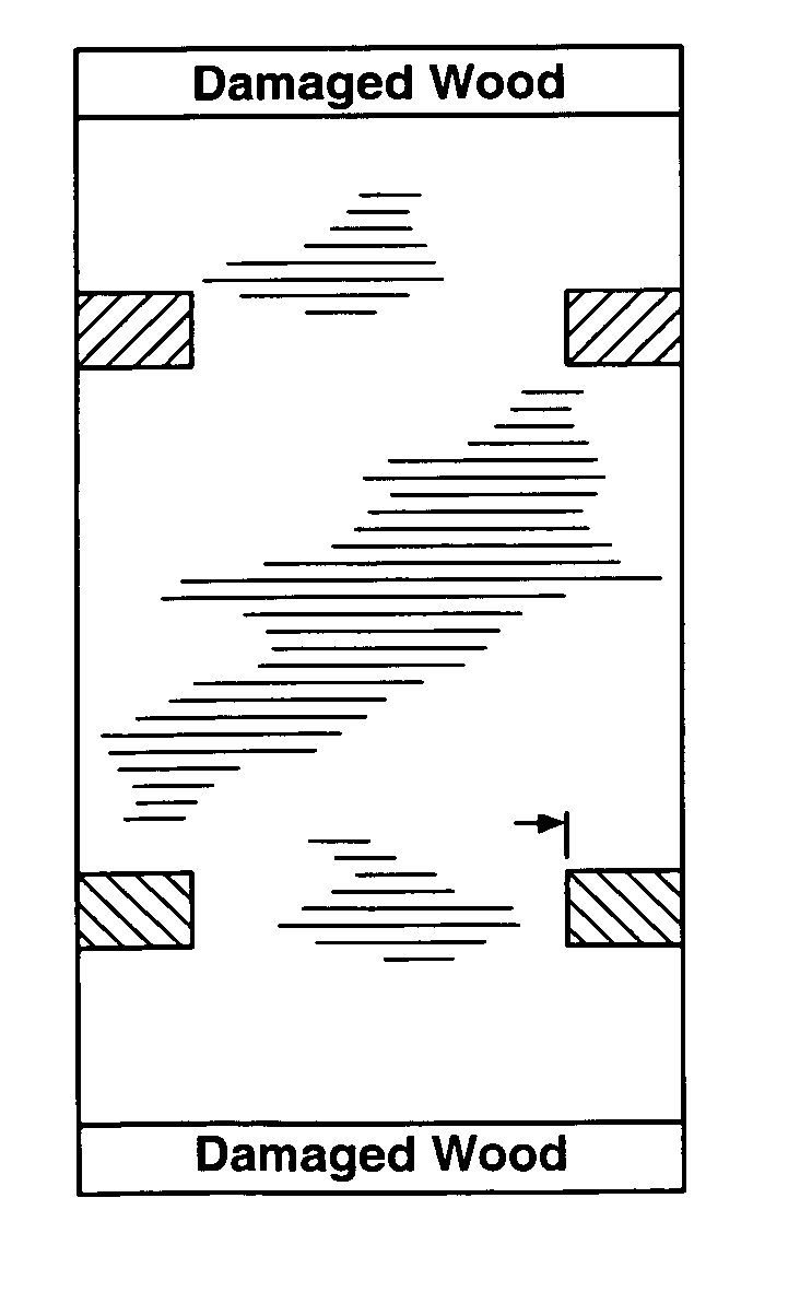
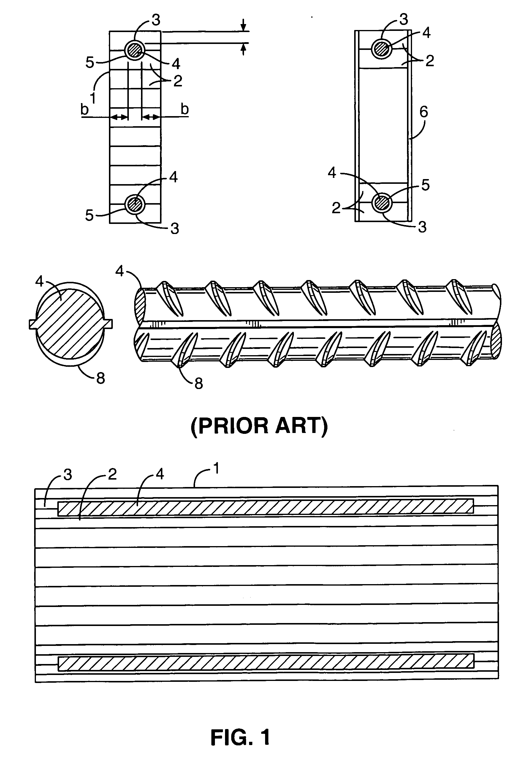
[0099]FIG. 1 shows the prior art beam as disclosed in the '366 patent. A computer model was made for this beam using an unpublished computer code designated herein as TRANSFORM X, which is a research program of limited capability that does not use finite element methods. TRANSFORM X is an adaptation of a computer code designed for other purposes and is discussed by Hernandez. (Ref. 15). Cheng reported good agreement between the method of Hernandez and his finite element methods. (Ref. 20) Because TRANSFORM X is a research code and has not been verified for general use, it was necessary to benchmark it for use in this specific application, and Gardner's data was the only available data relevant to embedded metal reinforced glue laminated beams. Gardner did not report calculated or measured stress data and without these data he was apparently unable to perform a failure mode and effects analysis. TRANSFORM X has the capability to analyze...


PUM


Abstract

The present invention relates to reinforced structural timbers. Such timbers may include an elongated structural member comprised of one or more elongated non-metallic composite materials and one or more pieces of embedded metal assembled to form a composite structural element.

Description

[0001] This application claims priority U.S. Provisional Patent Application No. 60 / 680,915 entitled “EMBEDED METAL REINFORCED STRUCTURAL TIMEBER” filed May 13, 2005, which is hereby incorporated by reference into this application.FIELD OF THE INVENTION [0002] The present invention relates to structural materials; more specifically to structural elements reinforced with metal. BACKGROUND BACKGROUND OF THE INVENTION—GENERAL INFORMATION [0003] The Forest Products Society (www.forestprod.org) is the leading professional society for the forest products industry. The Forest Products Journal and the online Journal of Forest Products Business Research are published by the Forest Products Society. The primary purpose of these journals is to provide a forum for the publication of timely, rigorous, technically sound, scientific research manuscripts that focus on the forest industry. The state of the art in the field of wooden structural elements at any given time is perhaps best evaluated in l...

Claims


Application Information

Patent Timeline
Patent Type & Authority Applications(United States)
Inventor BOLAND JAMES
Owner BOLAND JAMES
Why Eureka
Try Eureka