Elevator Door System
a technology for elevator doors and doors, applied in the direction of door/window protective devices, curtain suspension devices, shutters/movable grilles, etc., can solve problems such as damage to the aesthetic appearance of doors
- Summary
- Abstract
- Description
- Claims
- Application Information
AI Technical Summary
Benefits of technology
Problems solved by technology
Method used
Image
Examples
first embodiment
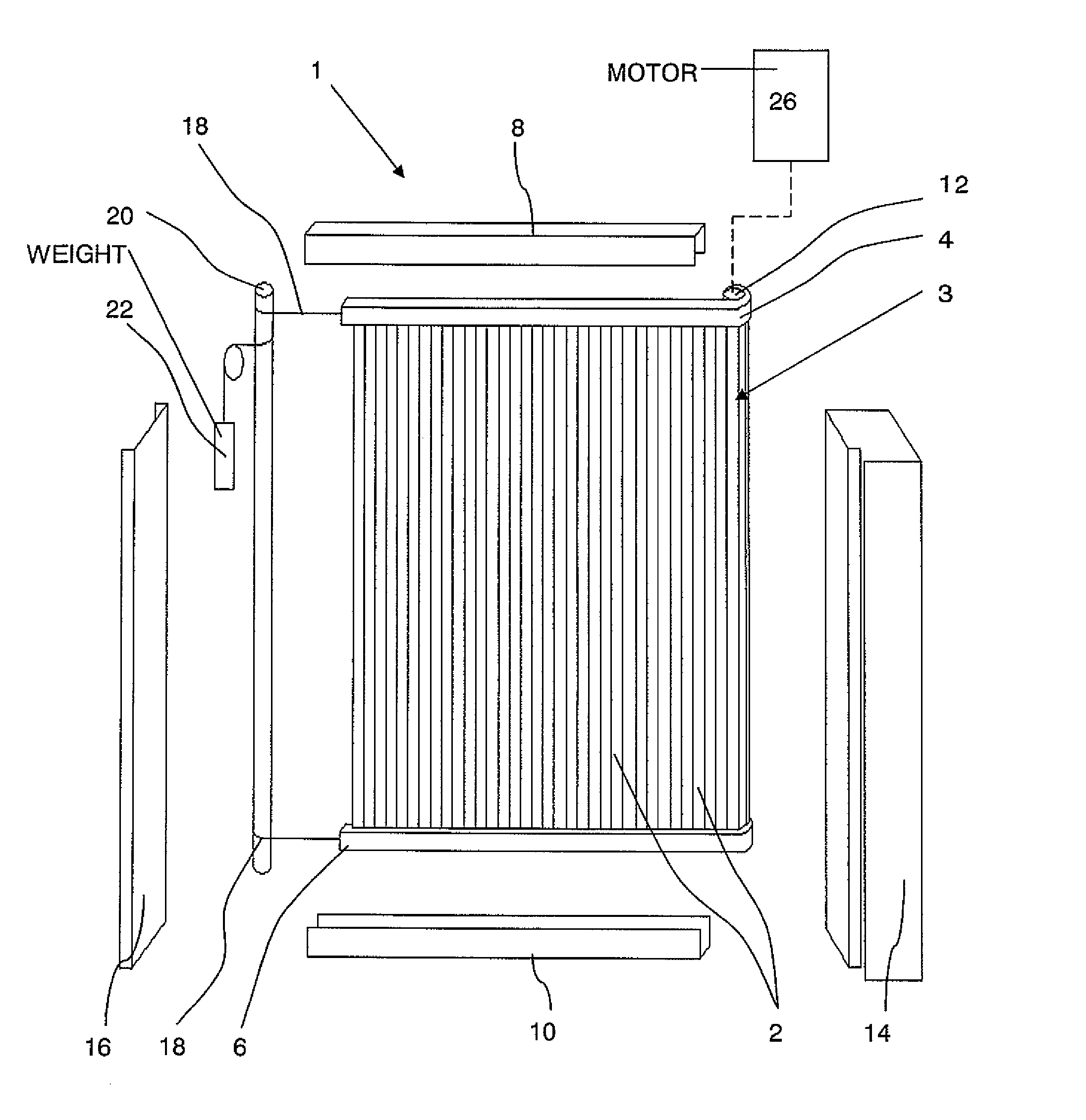
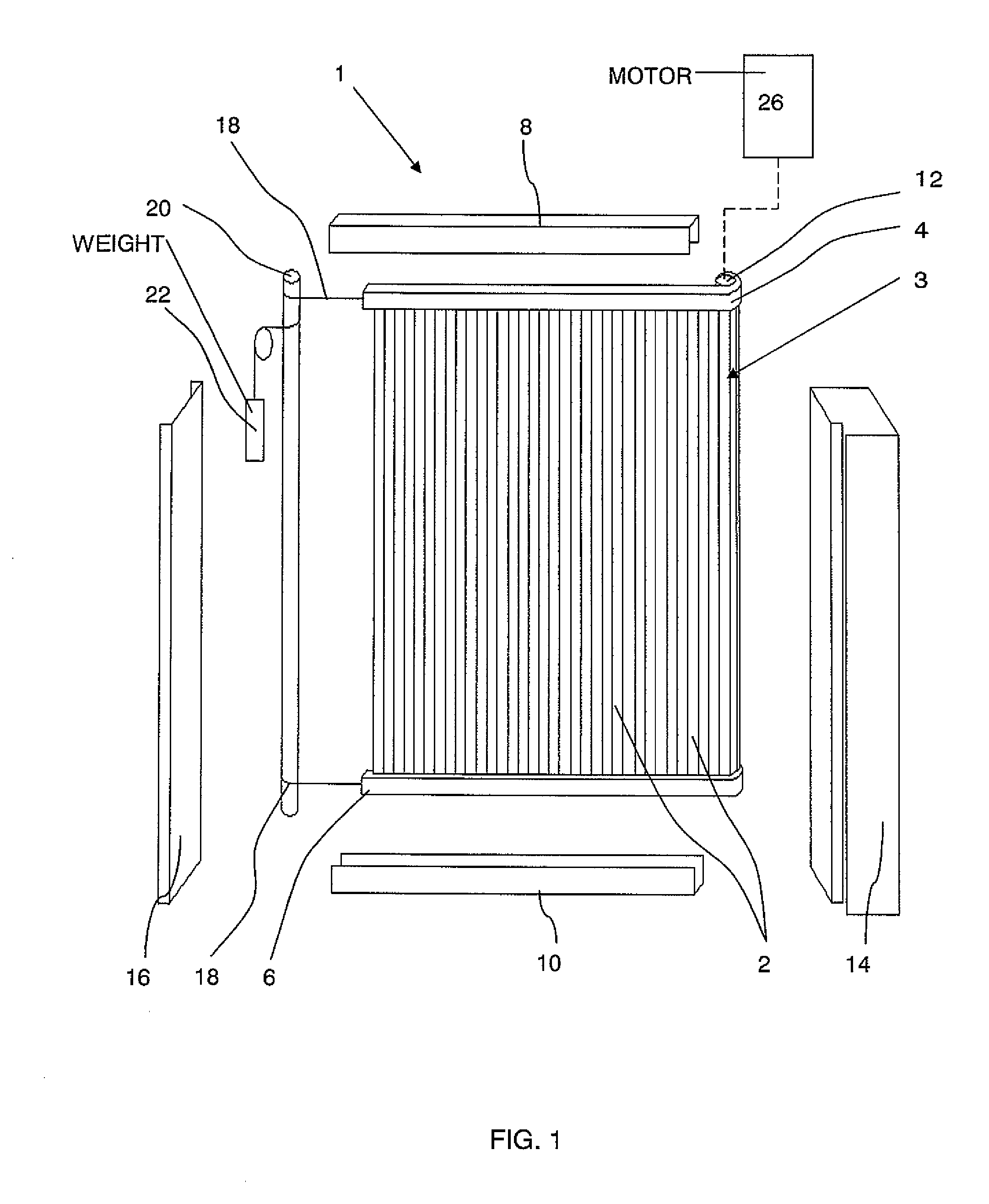
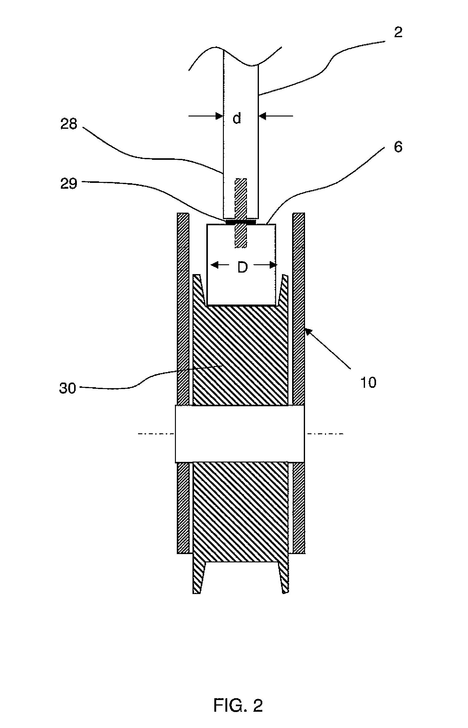
[0023]FIG. 1 is a general exploded perspective view of an elevator door system 1 incorporating a car door 3 according to the present invention which is used to control access to an elevator car (not shown) from a landing within a building. The door 3 is composed of a plurality of vertically aligned panels 2 each of which is preferably extruded from aluminium for its superior strength to weight ratio. The panels 2 are bound at their extremities by an upper belt of plastic material 4 and a lower belt of plastic material 6, respectively. The belts 4, 6 are attached at one end to a reel 12, rotation of which is controlled by a motor 26 to open and close the door 3. The opposing ends of the belts 4, 6 are attached by cables 18 to a counter-reel 20 which is biased in a door closing direction by a closing weight 22. The reel 12 and the counter-reel 20 are contained and retained within opposing door jambs 14 and 16, respectively.
[0024] During operation, the belts 4, 6 are guided along an up...
third embodiment
[0032]FIG. 4 is partial perspective view of an elevator door according to the present invention wherein the constituent panels 2 of the door 3 of the previous embodiments are replaced by pairs of glass panels 38 embedded in, affixed or bonded to either side of a plasticized interlayer 36 of polyvinylbutyral (PVB) material. The interlayer 36 is suspended between the upper belt 4 and the lower belt 6 respectively. Preferably, the upper and lower belts 4, 6 are manufactured integrally from the same PVB material as the interlayer 36.
fourth embodiment
[0033]FIG. 5 and FIG. 6 illustrate components of an elevator door system according to the present invention. Although the drawings and the following description refer only to the lower guide channel 10 and a lower transmission belt 40, it will be readily appreciated that the guidance at the upper section of the door 3 is achieved in the same manner.
[0034] As in the previously described embodiments, one end of the belt 40 is secured to the reel 12 and the other end is connected by the cable 18 to the counter-reel 20 as shown in the general arrangement of FIG. 1. Rather than the rectangular profile of the previous embodiments, the lower belt 40 used in this embodiment has a cropped V-shape. During operation, the belt 40 is guided by pulleys 44 rotatably mounted in the lower guide channel 10 and having converging flanges which engage with the side walls of the V-belt 40 to provide the necessary horizontal and vertical guidance.
[0035] Each of the door panels 2 is provided with one or m...
PUM
 Abstract
Description
Claims
Application Information
 - R&D
- Intellectual Property
- Life Sciences
- Materials
- Tech Scout
- Unparalleled Data Quality
- Higher Quality Content
- 60% Fewer Hallucinations
Browse by: Latest US Patents, China's latest patents, Technical Efficacy Thesaurus, Application Domain, Technology Topic, Popular Technical Reports.
© 2025 PatSnap. All rights reserved.Legal|Privacy policy|Modern Slavery Act Transparency Statement|Sitemap|About US| Contact US: help@patsnap.com


