Variable nozzle mechanism

a nozzle mechanism and variable technology, applied in the direction of liquid fuel engines, machines/engines, reaction engines, etc., can solve the problems of generating an impact load, damage to the drive ring, and the processing accuracy of the inner diameter may be deteriorated, so as to reduce the risk of damage, reduce the amount of wear and the driving force, and rotate more smoothly

Active Publication Date: 2010-08-12
MITSUBISHI HEAVY IND ENGINE & TURBOCHARGER LTD
View PDF6 Cites 20 Cited by
  • Summary
  • Abstract
  • Description
  • Claims
  • Application Information

AI Technical Summary

Benefits of technology

[0032]A variable geometry turbocharger according to the present invention includes the variable nozzle mechanism capable of reducing the risk of damage to the drive ring due to an external force and the contact load generated between the inner circumferential surfaces of the drive ring and the outer circumferential surface of the mount when the drive ring rotates, allowing the drive ring to rotate more smoothly, and reducing the amount of wear and the driving force.
[0033]With the variable geometry turbocharger according to the present invention, because the maintenance or replacement interval of the variable nozzle mechanism can be extended, the maintenance cost of the entire device (a variable geometry turbine and the variable geometry turbocharger) can be reduced.
[0034]With the variable geometry turbine and the variable geometry turbocharger including the variable nozzle mechanism according to the present invention, the reliability of the entire device is improved according to the improvement of the reliability of the variable nozzle mechanism.
[0035]With the variable geometry turbine and the variable geometry turbocharger including the variable nozzle mechanism according to the present invention, the weight of the entire device can be minimized according to the reduction in weight of the variable nozzle mechanism.
[0036]With the variable geometry turbine and the variable geometry turbocharger including the variable nozzle mechanism according to the present invention, the driving force for driving the drive ring is reduced, thus reducing the running costs.
[0037]The variable nozzle mechanism according to the present invention provides advantages in that, by reducing the weight of the drive ring, it is possible to reduce the risk of damage when an external force acts, as well as the contact load generated between the inner circumferential surface of the drive ring and the outer circumferential surface of the mount when changing the nozzle blade angle by rotating the drive ring, allowing smooth rotation of the drive ring and reduction in the amount of wear and the driving force.

Problems solved by technology

However, when the drive ring receives vibrations from outside, it collides with the surrounding parts contacting with the drive ring, with a gap therebetween, generating an impact load.
If the vibrations of the engine become large, the contact load is large, resulting in damage to the drive ring in some cases.
However, when providing the notch at the inner diameter, the processing accuracy of the inner diameter may be deteriorated.
As a result, a large contact force may be generated between the drive ring and the mount even when a small driving force for rotating the drive ring is applied.
Accordingly, an excessive frictional resistance due to rotation is generated, possibly causing a problem of difficulty in rotation.

Method used


Image

  • Variable nozzle mechanism
  • Variable nozzle mechanism
  • Variable nozzle mechanism

Examples


first embodiment

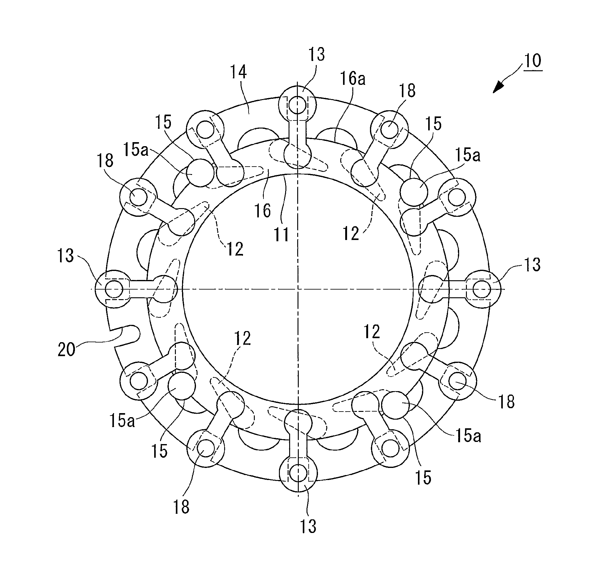
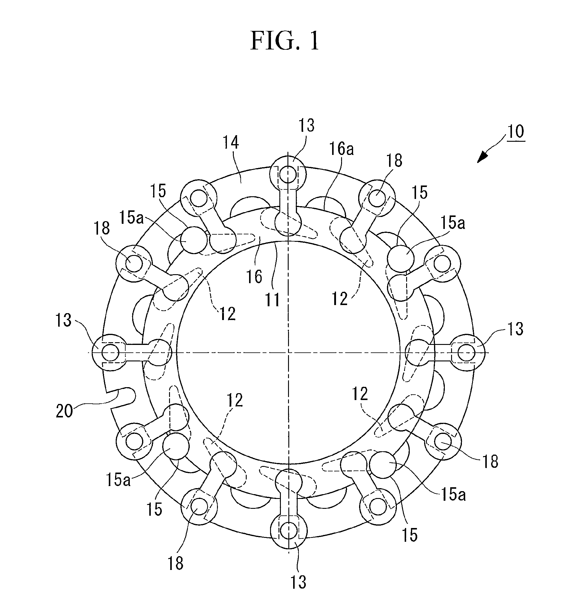
[0048]a variable nozzle mechanism according to the present invention will be described below with reference to FIGS. 1 and 2.

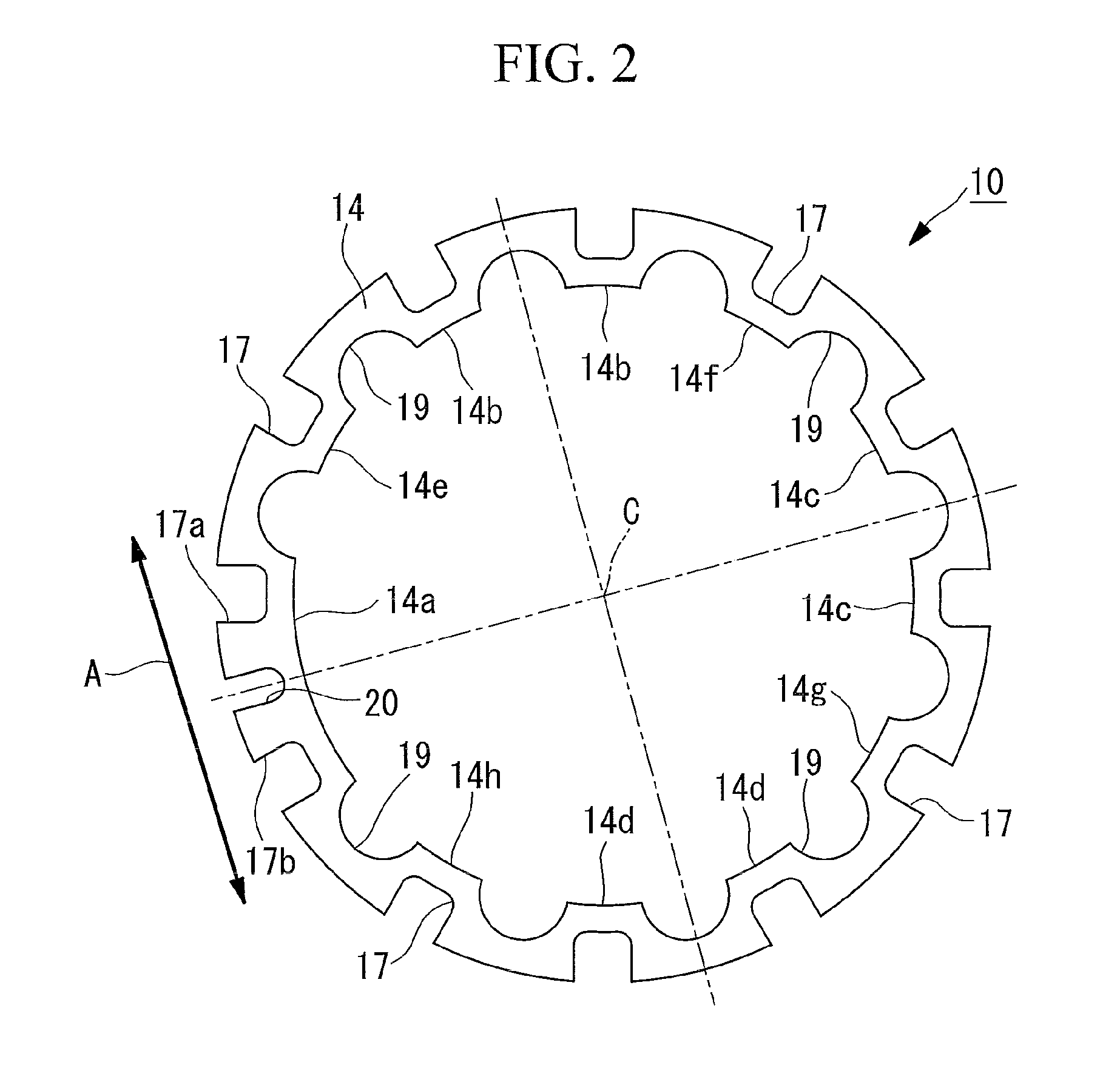
[0049]FIG. 1 is a plan view of principal parts of the variable nozzle mechanism according to this embodiment, and FIG. 2 is a plan view of a drive ring constituting the variable nozzle mechanism according to this embodiment.

[0050]The variable nozzle mechanism has a function of changing a flow speed of combustion gas (fluid) into a turbine rotor by rotating a nozzle to change a nozzle-blade angle and is used in a variable geometry turbine constituting a variable geometry turbocharger (for example, an exhaust-gas turbine-supercharger), not shown in the drawing.

[0051]The variable geometry turbocharger includes the variable geometry turbine and a compressor as main components.

[0052]The variable geometry turbine and the compressor are connected via a bearing housing, and a turbine rotor rotatably supported by a bearing is inserted into the bearing housing.

[0053]The...

second embodiment

[0076]a variable nozzle mechanism according to the present invention will be described with reference to FIG. 3.

[0077]As shown in FIG. 3, a variable nozzle mechanism 30 according to this embodiment differs from that according to the first embodiment described above in that, instead of the drive ring 14, a drive ring 31 is provided. Other components are the same as those in the above described first embodiment; therefore, a description thereof is omitted here.

[0078]The drive ring 31 has inner circumferential surfaces 14e, 14f, 14g, and 14h and other inner circumferential surfaces 14a, 14b, 14c, and 14d. Plate thicknesses of portions located between these inner circumferential surfaces 14e, 14f, 14g, and 14h and the first recesses 17 are formed so as to be larger than the plate thicknesses located between these inner circumferential surfaces 14a, 14b, 14c, and 14d and the first recesses 17, 17a, 17b and the third recess 20, forming thick portions 32.

[0079]Examples of methods for incre...

third embodiment

[0085]a variable nozzle mechanism according to the present invention will be described with reference to FIGS. 4A and 4B.

[0086]As shown in FIGS. 4A and 4B, a variable nozzle mechanism 40 according to this embodiment differs from that according to the first embodiment described above in that, instead of the drive ring 14, a drive ring 41 is provided. Other components are the same as those in the first embodiment described above; therefore, descriptions thereof are omitted here.

[0087]The drive ring 41 has an inner circumferential surface of the third recess 20. The plate thickness of a portion surrounding the third recess 20 is formed so as to be larger than that of other portions, forming a thick portion 42.

[0088]Examples of methods for increasing the plate thickness include, for example, bending back a portion protruding outward in the radial direction inward in the radial direction (see FIG. 4A), or forming a step when making the drive ring 41.

[0089]With the variable nozzle mechani...


PUM


Abstract

When changing a nozzle blade angle by rotating a drive ring, a contact load generated between an inner circumferential surface of the drive ring and an outer circumferential surface of a mount can be reduced, allowing the drive ring to rotate smoothly and reducing the amount of wear and a driving force. It is also possible to reduce an impact force, such as engine vibrations, generated at the drive ring when an external force acts, reducing the risk of damage. A plurality of notches (19) are provided at an inner rim of the drive ring (14), and, among inner circumferential surfaces (14a, 14b, 14c, 14d, 14e, 14f, 14g, and 14h) located between the notches (19), when a driving force for rotating the drive ring (14) is applied, the inner diameters of the inner circumferential surfaces (14e, 14f, 14g, and 14h) where the contact load with the outer circumferential surface of a mount becomes large are made larger than the outer diameter of the outer circumferential surface.

Description

BACKGROUND OF THE INVENTION[0001]1. Field of the Invention[0002]The present invention relates to a variable nozzle mechanism that has a function of changing a flow speed of combustion gas (fluid) into a turbine rotor by rotating a nozzle to change a nozzle blade angle and that is used in variable geometry turbines constituting a variable geometry turbocharger (for example, exhaust-gas turbine-supercharger).[0003]2. Description of Related Art[0004]A known variable nozzle mechanism used for variable geometry turbines is disclosed, for example, in Patent Documents 1 and 2.[0005]Patent Document 1: Japanese Unexamined Patent Application, Publication No. 2006-161811[0006]Patent Document 2: Japanese Unexamined Patent Application, Publication No. 2004-270472BRIEF SUMMARY OF THE INVENTION[0007]In the invention disclosed in the above-described Patent Documents, the inner diameter of a drive ring is made slightly larger than the outer diameter of a mount (supporting member).[0008]A turbocharge...

Claims


Application Information

Patent Timeline
Patent Type & Authority Applications(United States)
IPC IPC(8): F01D17/16
CPCF01D17/165F05D2220/40F05D2260/30F05D2250/19F05D2260/56F05D2250/182
Inventor HAYASHI, NORIYUKIJINNAI, YASUAKISUZUKI, HIROSHIISHII, YUKI
Owner MITSUBISHI HEAVY IND ENGINE & TURBOCHARGER LTD
Why Eureka
Try Eureka