Cup holding device

a technology for holding devices and cups, which is applied in the direction of passenger space, transportation and packaging, gas blowing apparatus, etc., can solve the problems of large tray, difficult to take a countermeasure for the load, and difficult to move smoothly, so as to improve the holding characteristic and the appearance improve the design flexibility, and make the tray small without affecting the holding characteristic and the effect of the cup holding devi

Active Publication Date: 2005-01-06
NIFCO INC
View PDF4 Cites 20 Cited by
  • Summary
  • Abstract
  • Description
  • Claims
  • Application Information

AI Technical Summary

Benefits of technology

[0017] The holding member is lifted for a length determined by the height of the upward inclined portions of the guiding grooves at the terminal ends thereof and the length of the vertical holes of the escape holes. Therefore, in the structure, the tray is independently moved in the front to rear direction with respect to the holding member corresponding to the length of the horizontal holes of the escape holes, thereby improving design flexibility. As a result, it is possible to make the tray small without impairing the holding characteristic and the appearance of the cup holding device. It is also possible to hold and lift the holding member in the substantially horizontal state with respect to the tray, thereby improving the holding characteristic. The holding member is lifted according to the shapes of the escape holes and guiding grooves guiding the shaft portions. Accordingly, a spring member in the conventional cup holding device may be omitted, or it is possible to reduce an urging force of the urging member, thereby simplifying and improving the operation.

Problems solved by technology

However, the holding member 52 is urged upwardly with a spring member with the pins 53 as supporting points, and it is necessary to provide the spring member with a considerably large urging force, thereby making it difficult to move smoothly.
When the device has a structure in which the holding member is vertically moved with respect to the tray through a parallel link, it is difficult to take a countermeasure for the load F described above, and the tray becomes large.

Method used


Image

  • Cup holding device
  • Cup holding device
  • Cup holding device

Examples


Embodiment Construction

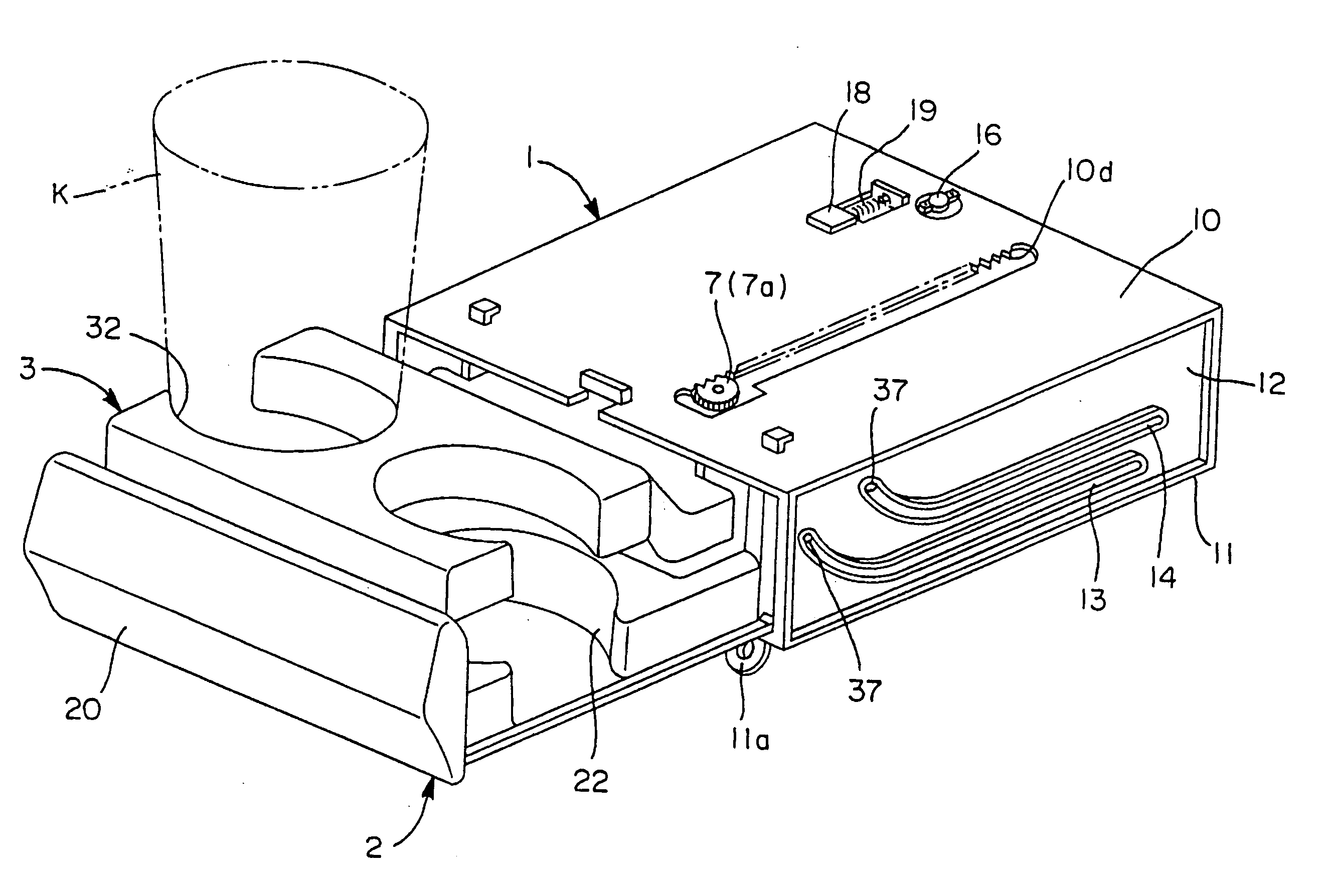
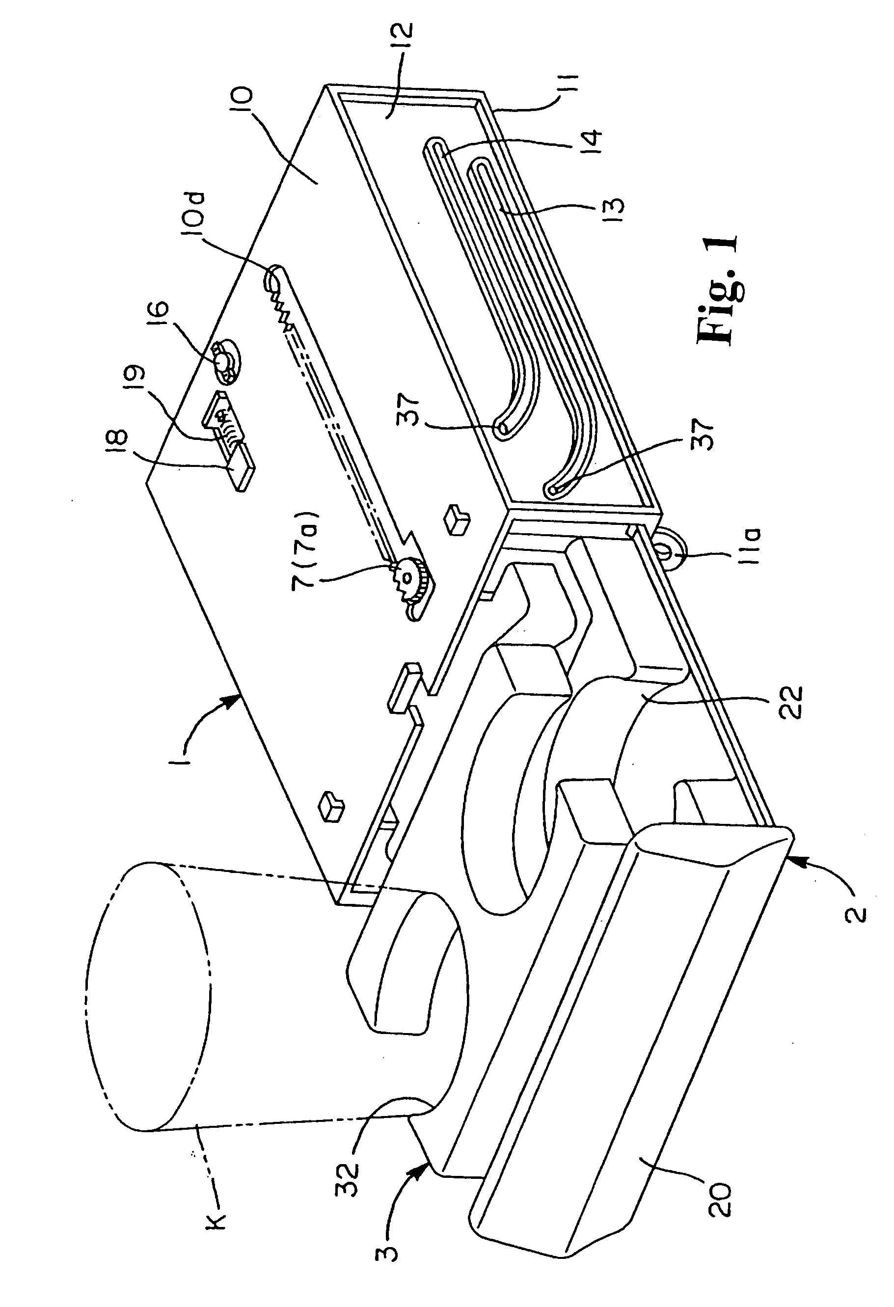
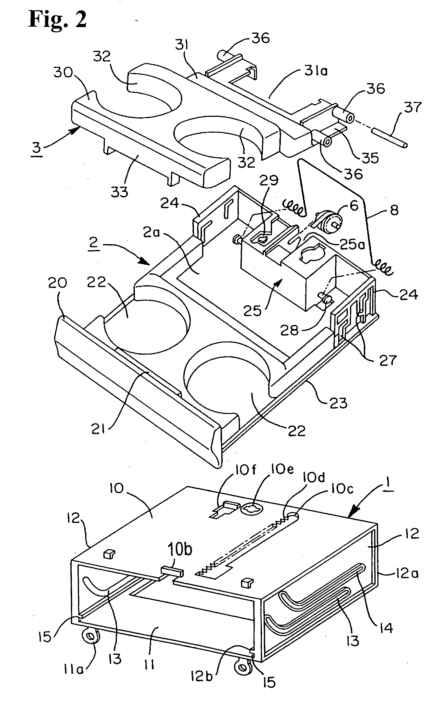
[0025] Hereunder, embodiments of the invention will be described with reference to the accompanying drawings. FIGS. 1 and 2 are schematic views showing a structure of a cup holding device. FIG. 3(a) is a plan view of a case; FIG. 3(b) is a plan view of the tray; and FIG. 3(c) is a side view of the tray. FIGS. 4(a) to 4(c) are views showing a detailed structure of the cup holder device, wherein FIG. 4(a) is a plan view of a holding member thereof, FIG. 4(b) is a side view of the holding member, and FIG. 4(c) is a sectional view taken along line 4(c)-4(c) in FIG. 4(a). FIGS. 5(a) and 5(b) are views showing a rib and a rib portion to be supported, wherein FIG. 5(a) is a partially exploded perspective view showing the rib formed on the tray and the rib portion to be supported formed on the holding member, and FIG. 5(b) is a partial perspective view showing a state where the rib engages the rib portion to be supported. FIGS. 6(a) to 6(c) show main movements of the cup holder device. In t...


PUM


Abstract

A cup holding device includes a storage case having a front opening; a tray for placing a container movable between a drawn position where the tray is drawn forward from the storage case and a storage position where the tray is stored in the storage case; a holding member attached to the tray for holding the container and movable between a non-usable position where the holding member is retained in the tray and a usable position where the holding member rises above the tray; and a supporting rib. The rib is disposed at a forward end of the tray for supporting a forward end of the holding member when the tray moves forward to the drawn position and the holding member moves to the usable position, and is situated in a space formed in the holding member when the holding member is at the non-usable position.

Description

BACKGROUND OF THE INVENTION AND RELATED ART STATEMENT [0001] The present invention relates to a cup holder or cup holding device disposed in a compartment of an automobile or the like and suitable for holding a cup or the like. [0002]FIG. 7 shows a conventional cup holding device disclosed in Japanese Patent No. 2794389. The cup holding device includes a case (retainer) 50 with a front opening; a tray 51 movable between a drawn position and a storage position with respect to the case 50; and a holding member 52 movable between a non-usable position overlapped with the tray 51 and stored in the case 50 and a usable position extending upwardly through a forward movement of the tray 51. [0003] The holding member 52 holds a periphery of a container K placed on the tray 51 through a hole of a holding portion 52a at the usable position. The tray 51 includes a pair of attaching pieces 51a projecting from a bottom surface thereof, and moves with both sides thereof sliding along guiding rail...

Claims


Application Information

Patent Timeline
Patent Type & Authority Applications(United States)
IPC IPC(8): B60N3/10
CPCB60N3/102F41B11/80F41H9/04
Inventor KOGAMI, MITSURU
Owner NIFCO INC
Why Eureka
Try Eureka