Video endoscope

Pending Publication Date: 2022-03-10
OLYMPUS WINTER & IBE
View PDF0 Cites 0 Cited by
  • Summary
  • Abstract
  • Description
  • Claims
  • Application Information

AI Technical Summary

Benefits of technology

The patent describes a fastening mechanism for joining two parts together. The fastening element is designed to fit snugly into a cavity on one of the parts, creating a secure and easy way to attach the parts. The fastening element can move smoothly through the retaining body and into the cavity, making it simple to install.

Problems solved by technology

However, the problem arises that when the video endoscope is rotated, the image sensor also rotates.
This causes the horizontal position of the image displayed on a monitor, for example, to be lost, which can cause a physician using the system to lose orientation on the image.
For this purpose, threaded holes must be made in the retaining body, which is costly.
Being frictionally held means that there may be a frictional force between the fastening element and the base of the groove which counteracts removal of the fastening element from the groove.

Method used


Image

  • Video endoscope
  • Video endoscope

Examples


Embodiment Construction

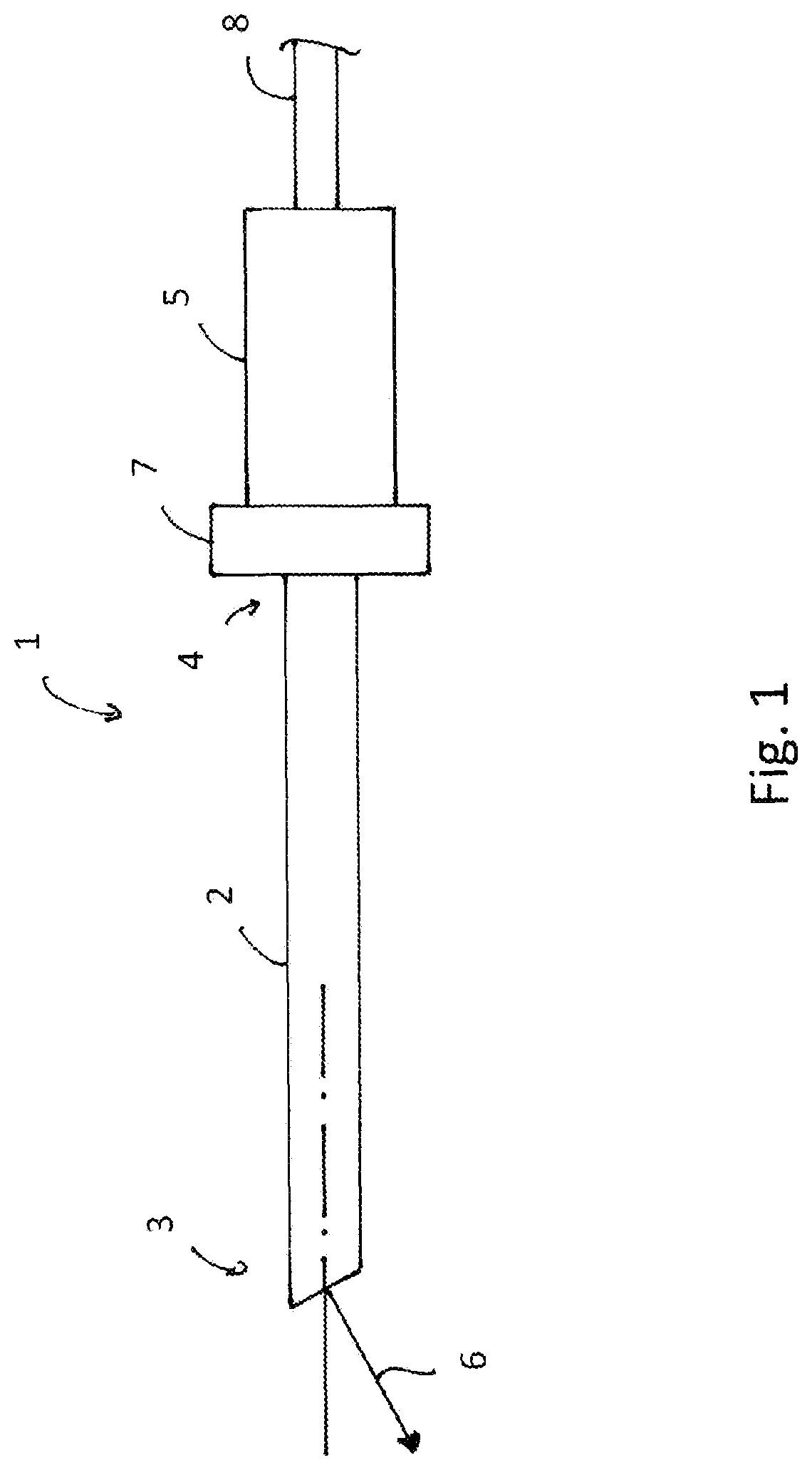
[0028]FIG. 1 shows a video endoscope 1. The video endoscope 1 has an elongated shaft 2 with a distal end 3 and a proximal end 4. At the proximal end 4 of the shaft 2, a handle 5 is disposed, by means of which the video endoscope 1 may be held and operated.

[0029]At the distal end 3 of the shaft 2, a lens not shown is disposed, the viewing direction of which is aligned in the direction of the arrow 6. By rotating the video endoscope 1, the viewing direction of the lens may be rotated about its longitudinal axis. A rotating ring 7 is used to control the horizontal position of an image captured by the video endoscope 1. The video signals generated by the video endoscope 1 are output via a cable 8.

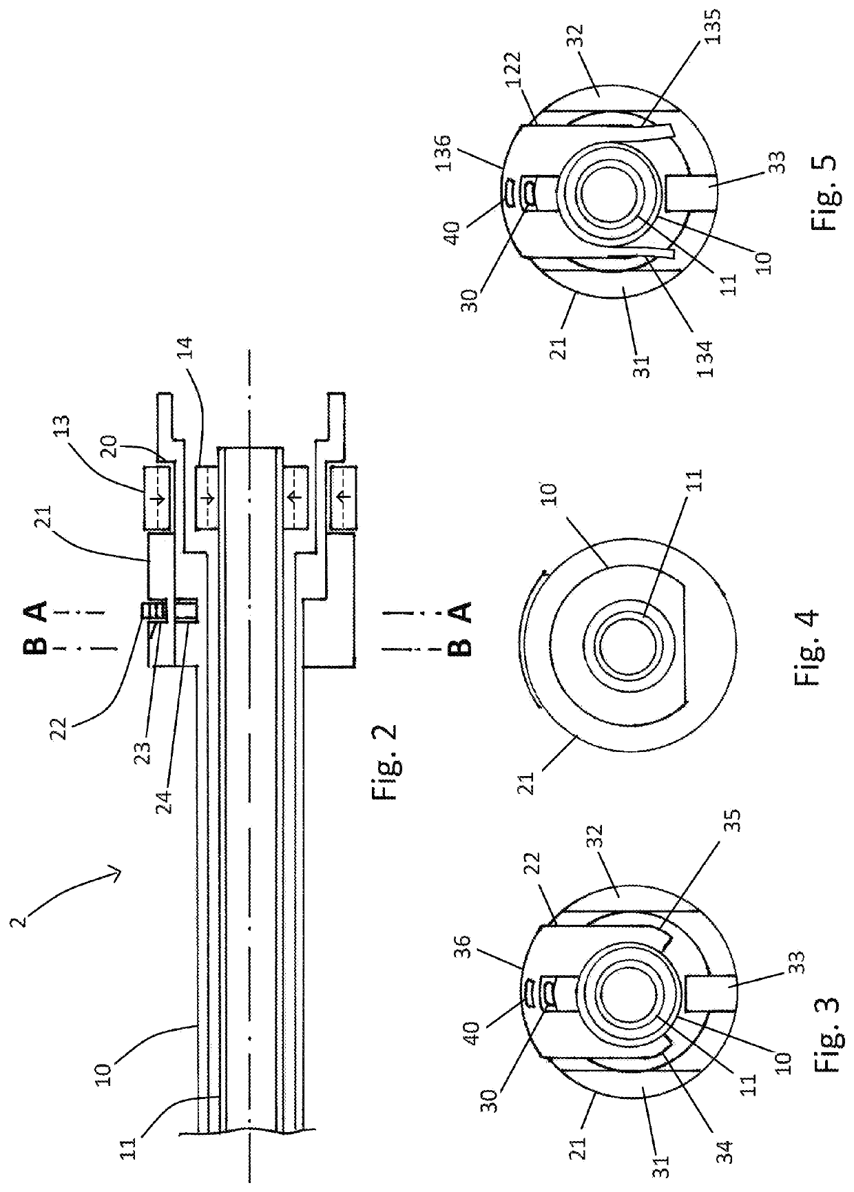
[0030]In FIG. 2, the internal structure of the shaft 2 is shown in simplified form. The shaft 2 comprises an outer shaft tube 10 and an inner shaft tube 11 disposed within the outer shaft tube 10. The lens is disposed at the distal end of the outer shaft tube 10, which is not shown. The outer s...


PUM


Abstract

A video endoscope including an elongated shaft, wherein the shaft includes at least one shaft tube, a magnetic ring surrounding the shaft tube is freely rotatably arranged in a region of a proximal end of the shaft tube, and the magnetic ring is axially fixed between a proximal stop shoulder of the shaft tube and a distal retaining body, and wherein the retaining body having a sleeve-like configuration and is placed onto the shaft tube from the distal direction. The shaft tube has an indentation in a region of the retaining body, and the retaining body is fastened on the shaft tube by a fastener which penetrates the retaining body and extends into the indentation.

Description

CROSS-REFERENCE TO RELATED APPLICATION[0001]The present application is based upon and claims the benefit of priority from PCT / EP2019 / 083760 filed on Dec. 4, 2019, which claims priority to DE 10 2019 100 147.1 filed on Jan. 4, 2019, the entire contents of each of which is incorporated herein by reference.BACKGROUNDField[0002]The present disclosure relates to a video endoscope and more particularly to a video endoscope with an elongated shaft, wherein the shaft comprises at least one shaft tube, a magnetic ring surrounding the shaft tube is freely rotatably arranged in the region of a proximal end of the shaft tube, and the magnetic ring is axially fixed between a proximal stop shoulder of the shaft tube and a distal retaining body, and wherein the retaining body has a sleeve-like configuration and is placed on the shaft tube from the distal direction.Prior Art[0003]Video endoscopes are used in medicine to examine and, if necessary, treat areas of a patient that are difficult to acces...

Claims


Application Information

Patent Timeline
IPC IPC(8): A61B1/00A61B1/05
CPCA61B1/00183A61B1/00073A61B1/00066A61B1/00179A61B1/05A61B1/0011A61B1/00071
Inventor THUEMEN, ALRUN
Owner OLYMPUS WINTER & IBE
Why Eureka
Try Eureka