Vehicle lighting device

Inactive Publication Date: 2022-03-31
ICHIA TECH
View PDF0 Cites 0 Cited by
  • Summary
  • Abstract
  • Description
  • Claims
  • Application Information

AI Technical Summary

Benefits of technology

The present invention provides a vehicle lighting device that overcomes the problems associated with conventional lighting devices. By using at least one lower or upper light-emitting element, the device is lighter and thinner. This is achieved by directing the light out of the device, making it more efficient and effective.

Problems solved by technology

Nevertheless, the aforementioned design of the conventional vehicle lighting device has a thicker overall thickness and heavier weight.

Method used


Image

  • Vehicle lighting device
  • Vehicle lighting device
  • Vehicle lighting device

Examples


first embodiment

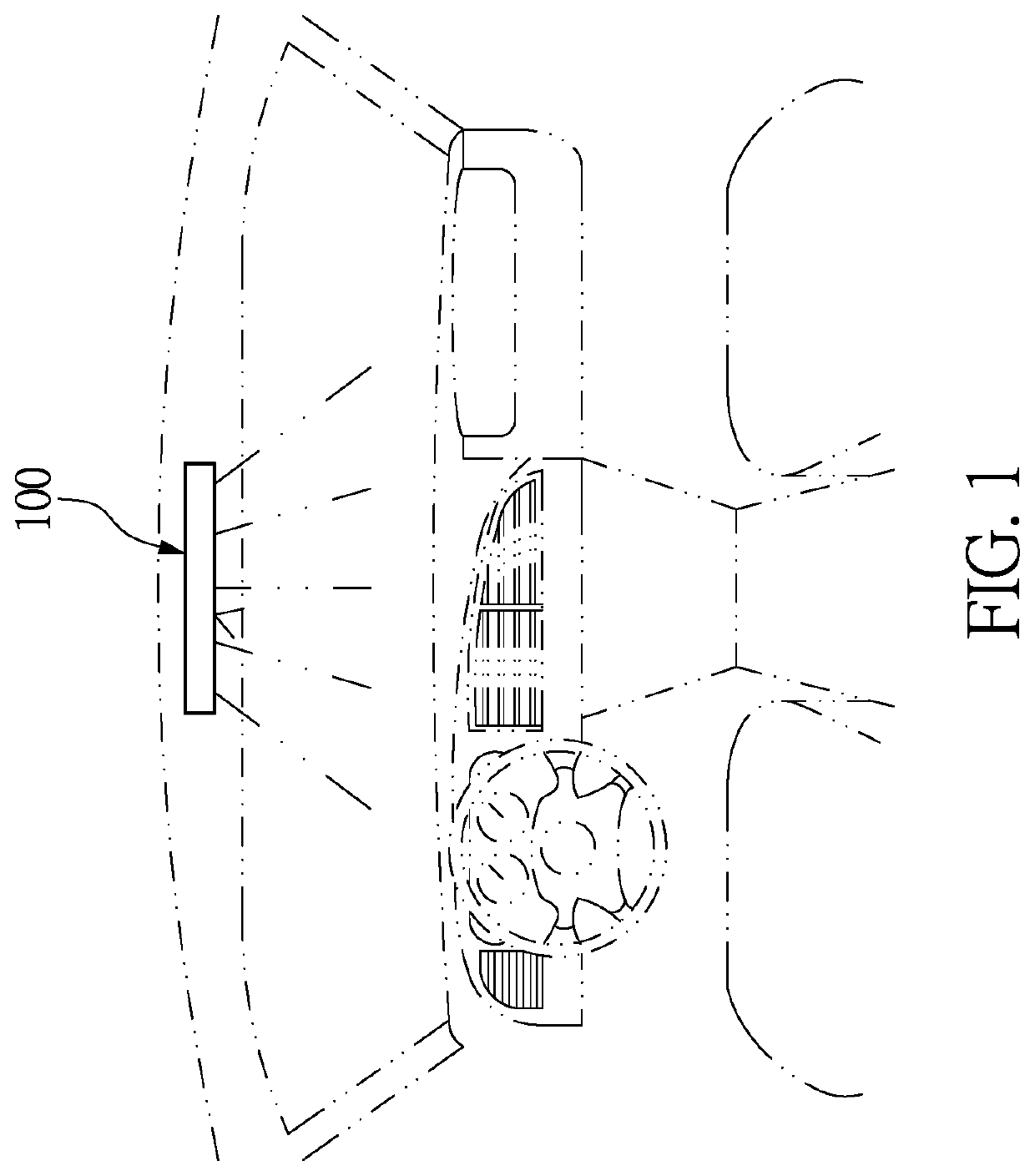
[0022]Referring to FIG. 1 to FIG. 6, a first embodiment of the present disclosure provides a vehicle lighting device 100, in particular, a vehicle lighting device 100 that is installed on a vehicle body and operated by touch (as shown in FIG. 1). In other words, any touch device that is not used for lighting purposes is not the vehicle lighting device 100 of the present disclosure (e.g., smartphones or tablet computers).

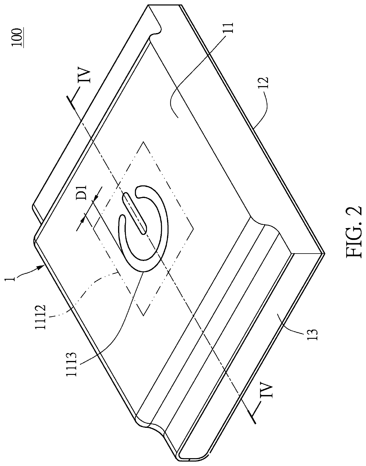
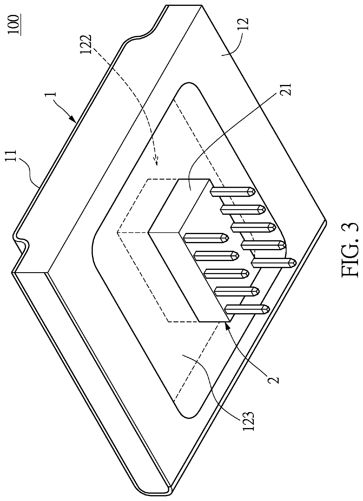
[0023]Referring to FIG. 1 to FIG. 3, the vehicle lighting device 100 includes a main body 1 and a connecting unit 2 that is electrically connected to the main body 1. Specifically, the connecting unit 2 is configured to electrically connect to a control circuit (not shown in the drawings), so that the control circuit can control the vehicle lighting device 100. The following description describes the structure and connection relation of each component of the vehicle lighting device 100.

[0024]Referring to FIG. 2 to FIG. 4, the main body 1 includes an upper film 11, a ...

second embodiment

[0036]Referring to FIG. 7 and FIG. 8, a second embodiment of the present disclosure provides a vehicle lighting device 100. The present embodiment is similar to the first embodiment, and the similarities between the present embodiment and the first embodiment will not be repeated. The differences between the present embodiment and the first embodiment are:

[0037]The connecting unit 2 in the present embodiment includes a lower connecting end 22 integrally connected to the lower covering portion 121, and the lower connecting end 22 has a lower printed circuit layer 221 facing the upper film 11. The lower printed circuit layer 221 is electrically connected to the lower conductive layer 1211, and the lower connecting end 22 is configured to electrically connect to the control circuit. In other words, the lower connecting end 22 will not be blocked by the light guide filler 13, so that the lower printed circuit layer 221 of the lower connecting end 22 can be directly electrically connecte...

third embodiment

[0038]Referring to FIG. 9, a third embodiment of the present disclosure provides a vehicle lighting device 100. The present embodiment is similar to the first embodiment, and the similarities between the present embodiment and the first embodiment will not be repeated herein. The differences between the present embodiment and the first embodiment are as follows.

[0039]The vehicle lighting device 100 further includes at least one upper light-emitting element 15 embedded in the light guide filler 13. The at least one upper light-emitting element 15 is located on a part of the setting region 1112 defined by orthogonally projecting on the upper conductive layer 1111, and the at least one upper light-emitting element 15 is electrically connected to the upper conductive layer 1111, and the at least one upper light-emitting element 15 can emit a light to the light-permeable layer 1113 through the light guide filler 13.

[0040]Specifically, the at least one upper light-emitting element 15 may ...


PUM


Abstract

A vehicle lighting device is provided. The vehicle lighting device includes a main body and a connecting unit. The main body has an upper film, a lower film, a light guide filler, and at least one lower light-emitting element. The upper film has a setting area and a light-permeable layer at a center of the setting area. A distance spaced apart between an edge of the light-permeable layer and an edge of the setting region is no more than 5 cm. The at least one lower light-emitting element is embedded in the light guide filler arranged between the lower film and the upper film and is located on a part of the setting region defined by orthogonally projecting the lower conductive layer onto the setting region. The connecting unit can electrically connect to a control circuit to control the at least one lower light-emitting element.

Description

FIELD OF THE DISCLOSURE[0001]The present disclosure relates to a lighting device, and more particularly to a vehicle lighting device.BACKGROUND OF THE DISCLOSURE[0002]A conventional vehicle lighting device has a contact plate, an additional circuit board, a plurality of light shielding members, and a plurality of light-emitting elements. The light shielding members arranged between the contact plate and the additional circuit board are spaced apart from each other. The conventional vehicle lighting device has a plurality of light channels that are formed between any two adjacent light shielding members. The light-emitting elements are each disposed on the additional circuit board and located in the light channels. When a finger touches the contact plate, a charge path is established, so that the contact plate generates a charge accumulation. The light-emitting elements are triggered according to an amount of the charge accumulation, and emit light out of the contact plate through th...

Claims


Application Information

Patent Timeline
IPC IPC(8): B60Q3/82F21V8/00B60Q3/51
CPCB60Q3/82G02B6/006B60Q3/51G02B6/0041G02B6/0083B60Q3/14B60Q3/64B60Q3/74G02B6/0021
Inventor CHEN, JEN-CHENGYU, SHIH-FUZHANG, YAN-HAI
Owner ICHIA TECH
Why Eureka
Try Eureka