Coaxial connector

Active Publication Date: 2022-10-13
BO JIANG TECH
View PDF7 Cites 0 Cited by
  • Summary
  • Abstract
  • Description
  • Claims
  • Application Information

AI Technical Summary

Benefits of technology

[0005]In response to the above-referenced technical inadequacy, the present disclosure provides a coaxial connector to improve an issue associated with a conventional high-frequency coaxial connecto

Problems solved by technology

That is, when the conventional high-frequency coaxial connector is used to transmit a high frequency signal having a frequency higher than 10 GHz, issues relating to convex waves can easily occur.
Therefore, compared to th

Method used


Image

  • Coaxial connector
  • Coaxial connector
  • Coaxial connector

Examples


Example

First Embodiment

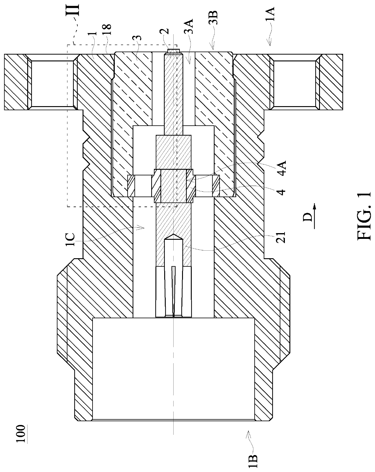
[0033]Referring to FIG. 1 to FIG. 5, a coaxial connector 100 of the present disclosure includes a shell 1, a core body 2, and a fixing member 3. The core body 2 is disposed in the fixing member 3, the fixing member 3 having the core body 2 disposed therein is disposed in the shell 1, and two ends of the core body 2 are exposed from the shell 1. One end of the coaxial connector 100 of the present embodiment is configured to be fixed to a circuit board, and another end of the coaxial connector 100 is configured to be mated by a related signal transmitting wire, but the manner of application of the coaxial connector 100 of the present disclosure is not limited thereto.

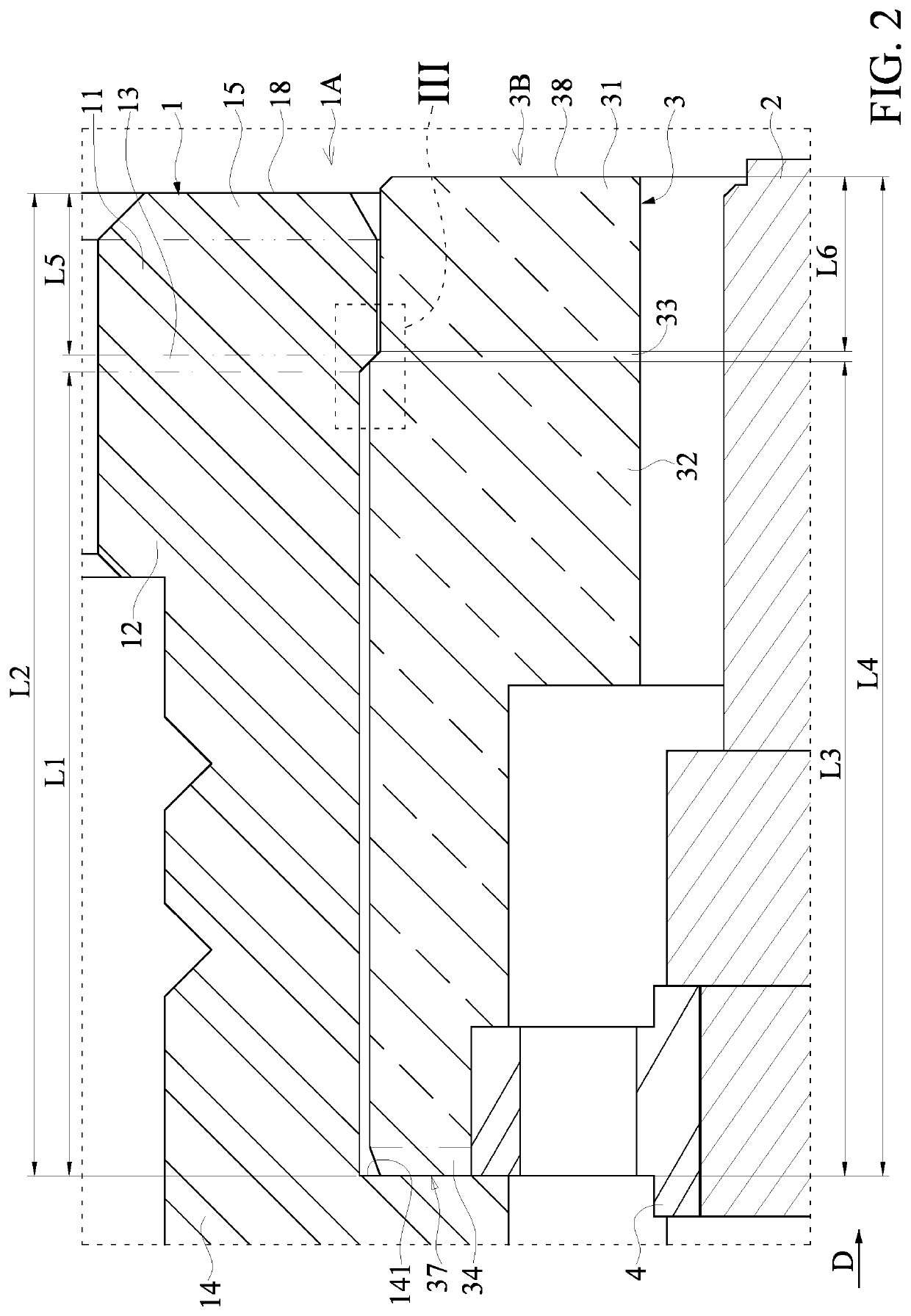
[0034]Referring to FIG. 1 to FIG. 4, the shell 1 defines a first end 1A and a second end 1B opposite to each other. The shell 1 has a central passage 1C penetrating through the shell 1 along an axial direction D. The central passage 1C is configured to accommodate the fixing member 3. The shell 1 includes ...

Example

Second Embodiment

[0051]Referring to FIG. 6 to FIG. 13, the differences between the present embodiment and the first embodiment are as follows.

[0052]The shell 1 includes the first annular portion 11, the second annular portion 12, the annular engaging portion 13, the annular abutting portion 14, an annular step difference portion 16, an annular connection portion 17, and the annular guiding portion 15. The shell 1 sequentially includes the annular guiding portion 15, the first annular portion 11, the annular engaging portion 13, the second annular portion 12, the annular step difference portion 16, the annular connection portion 17, and the annular abutting portion 14 from the first end 1A to the second end 1B. In other embodiments, the coaxial connector 100 of the present embodiment can be provided without at least one of the annular step difference portion 16, the annular connection portion 17, and the annular guiding portion 15.

[0053]The first annular portion 11 is arranged near t...

Example

Third Embodiment

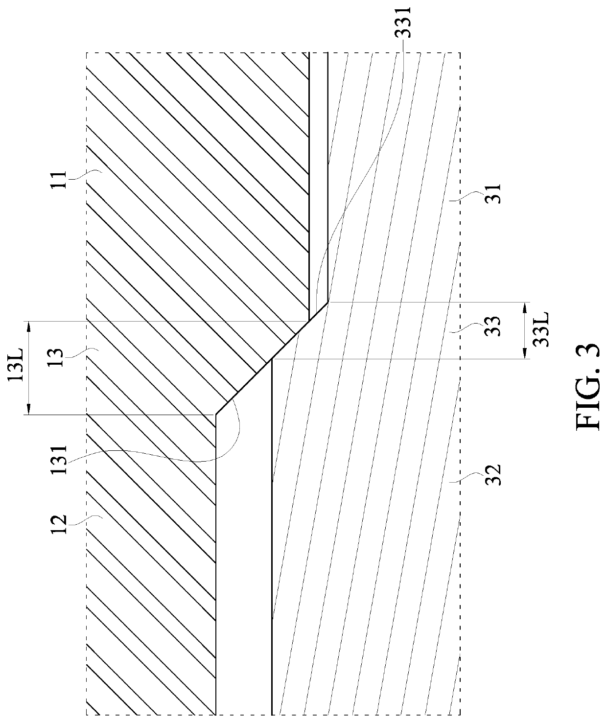
[0069]Referring to FIG. 14 to FIG. 20, one of the differences between the present embodiment and the above-mentioned second embodiment is as follows. The shell 1 sequentially includes the annular guiding portion 15, the first annular portion 11, the annular step difference portion 16, the annular connection portion 17, the annular engaging portion 13, the second annular portion 12, and the annular abutting portion 14 from the first end 1A to the second end 1B. The fixing member 3 sequentially includes a head portion 39, the first portion 31, the engaging portion 33, the second portion 32, and the guiding portion 34 from the third end 3B to the fourth end 3C. Ratios among a length 13L of the annular engaging portion 13, a length 16L of the annular step difference portion 16, a length 17L of the annular connection portion 17, the length 31L of the first portion 31, and the length 33L of the engaging portion 33 along the axial direction D are not limited to those shown ...


PUM


Abstract

A coaxial connector is provided. The coaxial connector includes a shell, a core body, and a fixing member. The shell has a central passage. The shell includes a first annular portion, a second annular portion, an annular engaging portion, and an annular abutting portion. The fixing member has a thru-hole.
The fixing member includes a first portion, a second portion, and an engaging portion. The core body fixedly penetrates through the thru-hole of the fixing member. An inner diameter of the annular engaging portion gradually increases from one end of the shell to another end of the shell. The annular engaging portion has a first annular inclined surface, and the fixing member has a second annular inclined surface. The fixing member is engaged in the central passage, and the first annular inclined surface and the second annular inclined surface abut against each other.

Description

CROSS-REFERENCE TO RELATED PATENT APPLICATION[0001]This application claims the benefit of priority to Taiwan Patent Application No. 110203738, filed on Apr. 7, 2021. The entire content of the above identified application is incorporated herein by reference.[0002]Some references, which may include patents, patent applications and various publications, may be cited and discussed in the description of this disclosure. The citation and / or discussion of such references is provided merely to clarify the description of the present disclosure and is not an admission that any such reference is “prior art” to the disclosure described herein. All references cited and discussed in this specification are incorporated herein by reference in their entireties and to the same extent as if each reference was individually incorporated by reference.FIELD OF THE DISCLOSURE[0003]The present disclosure relates to a coaxial connector, and more particularly to a coaxial connector applicable to transmit a hi...

Claims


Application Information

Patent Timeline
IPC IPC(8): H01R24/40H01R13/629H01R13/502H01R13/40
CPCH01R24/40H01R13/629H01R13/502H01R13/40H01R2103/00H01R24/50H01R9/05
Inventor CHIANG, CHANG-HUI
Owner BO JIANG TECH
Why Eureka
Try Eureka