Outdoor electronic apparatus and sunshade thereof

Pending Publication Date: 2022-09-08
WISTRON NEWEB
View PDF0 Cites 0 Cited by
  • Summary
  • Abstract
  • Description
  • Claims
  • Application Information

AI Technical Summary

Benefits of technology

The present disclosure provides an outdoor electronic apparatus and sunshade that improves on conventional outdoor electronic apparatuses. The sunshade allows air to flow smoothly through its structure, which results in better convection for the electronic device. The shielding structures in the sunshade effectively shield sunlight while still allowing air to flow through the top convection holes. The technical effects of this invention include smoother airflow, improved cooling efficiency, and better protection against sunlight.

Problems solved by technology

A conventional outdoor electronic apparatus often experiences a rise in temperature due to exposure to sunlight.
However, the sunshade of the conventional outdoor electronic apparatus often decreases a heat dissipation effect from convection of the electronic device.

Method used


Image

  • Outdoor electronic apparatus and sunshade thereof
  • Outdoor electronic apparatus and sunshade thereof
  • Outdoor electronic apparatus and sunshade thereof

Examples


first embodiment

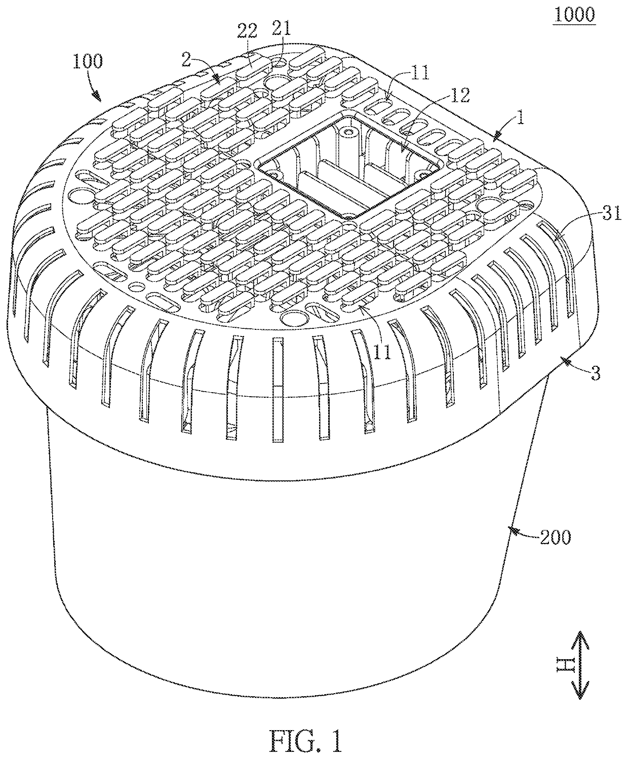
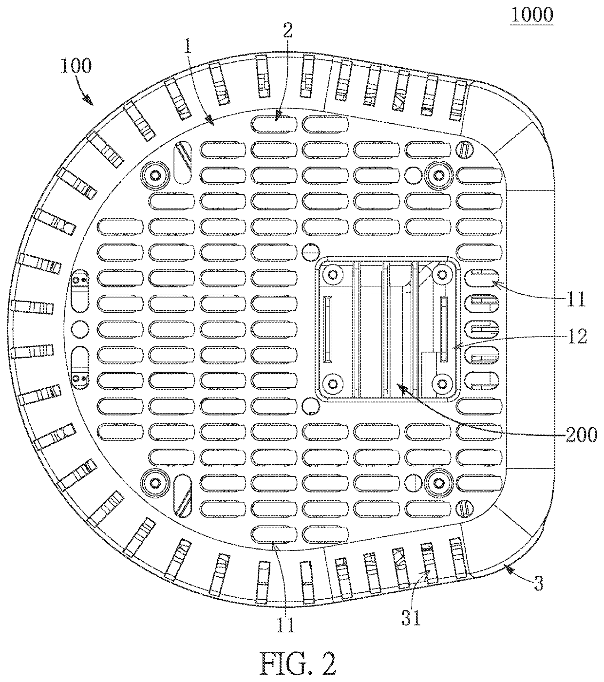
[0029]Referring to FIG. 1 to FIG. 7, a first embodiment of the present disclosure provides an outdoor electronic apparatus 1000 that preferably excludes any indoor electronic apparatus. The outdoor electronic apparatus 1000 includes a sunshade 100 and an electronic device 200 that is assembled to the sunshade 100, but the type of the electronic device 200 can be changed or adjusted according to design requirements.

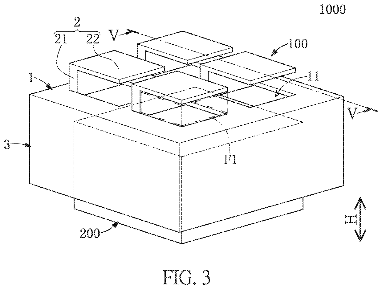
[0030]It should be noted that the sunshade 100 in the present embodiment is described in cooperation with the electronic device 200, but the present disclosure is not limited thereto. For example, in other embodiments of the present disclosure, the sunshade 100 can be independently used (e.g., sold) or can be used in cooperation with other devices. In the present embodiment, FIG. 1 and FIG. 2 show a specific structure of the outdoor electronic apparatus 1000, and FIG. 3 to FIG. 7 show schematic structures of the outdoor electronic apparatus 1000 for clearly describing most...

second embodiment

[0049]Referring to FIG. 8 to FIG. 10, a second embodiment of the present disclosure is similar to the first embodiment of the present disclosure. For the sake of brevity, descriptions of the same components in the first and second embodiments of the present disclosure (e.g., the top shield 1, the shielding structures 2, and the electronic device 200) will be omitted herein, and the following description only discloses different features between the first and second embodiments.

[0050]In the present embodiment, the lateral shield 3 is in a C-shape and surrounds a part of the heat dissipating space S, so that the lateral shield 3 and the top portion of the electronic device 200 have a C-shaped space C there-between that is in spatial communication with the heat dissipating space S. The lateral shield 3 does not cover a part of the heat dissipating space S along a predetermined direction P perpendicular to the vertical direction H, and does not cover a part of the electronic device 200 ...

third embodiment

[0052]Referring to FIG. 11 to FIG. 13, a third embodiment of the present disclosure is similar to the first embodiment of the present disclosure. For the sake of brevity, descriptions of the same components in the first and third embodiments of the present disclosure (e.g., the top shield 1, the shielding structures 2, and the electronic device 200) will be omitted herein, and the following description only discloses different features between the first and third embodiments.

[0053]In the present embodiment, the lateral shield 3 includes a shielding segment 32 and an end segment 33. The shielding segment 32 in the present embodiment is in a C-shape and surrounds a part of the heat dissipating space S, so that the lateral shield 3 and the top portion of the electronic device 200 have a C-shaped space C there-between that is in spatial communication with the heat dissipating space S. The end segment 33 is connected to (or extends from) the shielding segment 32 and is located in a notch...


PUM


Abstract

An outdoor electronic apparatus and a sunshade thereof are provided. The sunshade is assembled to an electronic device, and includes a top shield and a plurality of shielding structures formed on the top shield. The top shield has a plurality of top convection holes at least partially corresponding in position to the shielding structures. An edge of any one of the shielding structures and a hole edge of the corresponding top convection hole jointly define a first interface region having an outflow area. The sunshade and an outer surface of the electronic device jointly define a second interface region that is in spatial communication with the first interface regions of the top shield and that has an inflow area. The inflow area is greater than or equal to at least 20% of a sum of the outflow areas of the top shield.

Description

CROSS-REFERENCE TO RELATED PATENT APPLICATION[0001]This application claims the benefit of priority to Taiwan Patent Application No. 110107519, filed on Mar. 3, 2021. The entire content of the above identified application is incorporated herein by reference.[0002]Some references, which may include patents, patent applications and various publications, may be cited and discussed in the description of this disclosure. The citation and / or discussion of such references is provided merely to clarify the description of the present disclosure and is not an admission that any such reference is “prior art” to the disclosure described herein. All references cited and discussed in this specification are incorporated herein by reference in their entireties and to the same extent as if each reference was individually incorporated by reference.FIELD OF THE DISCLOSURE[0003]The present disclosure relates to an electronic apparatus, and more particularly to an outdoor electronic apparatus and a sunsh...

Claims


Application Information

Patent Timeline
IPC IPC(8): E06B9/68
CPCE06B9/68E06B2009/6827A45B2023/0093A45B23/00H05K7/20127H05K5/03
Inventor KU, YU-FUWU, YI-HSUAN
Owner WISTRON NEWEB
Why Eureka
Try Eureka