
Probe card device and neck-like probe thereof

Active Publication Date: 2021-07-22
CHUNGHWA PRECISION TEST TECH
View PDF0 Cites 0 Cited by
  • Summary
  • Abstract
  • Description
  • Claims
  • Application Information

AI Technical Summary

Benefits of technology

This patent provides a probe card device and a neck-like probe to improve the problems associated with conventional conductive probes. The conductive pin has two long slots to control the abutting force and protect the ring-shaped insulator from scratches. The minimum distance of the conductive pin can be adjusted to change the reaction force, and the ratio of the minimum distance to the maximum distance can be controlled to maintain signal transmission performance. These improvements enhance the reliability and accuracy of the probe card device and the neck-like probe.

Problems solved by technology

However, the cooperative configuration between the conductive pin and the insulating layer of the conventional conductive probe has been in use for many years, so that further development and progress of probe card devices are impeded.

Method used


Image

  • Probe card device and neck-like probe thereof
  • Probe card device and neck-like probe thereof
  • Probe card device and neck-like probe thereof

Examples


first embodiment

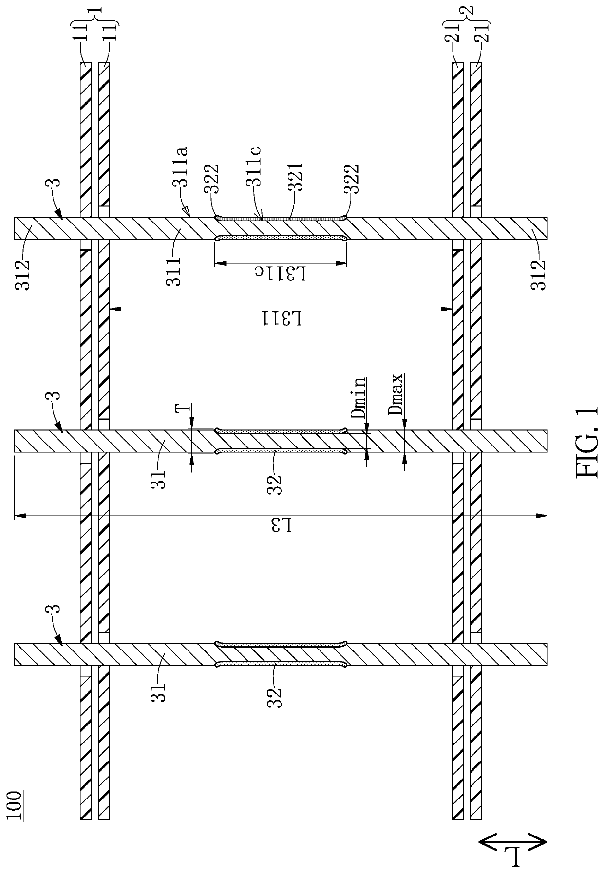
[0027]Referring to FIG. 1 to FIG. 9, a first embodiment of the present disclosure provides a probe card device 100. As shown in FIG. 1 to FIG. 3, two opposite sides of the probe card device 100 are configured to abut against a space transformer and a device under test (DUT) (e.g., a semiconductor wafer), respectively. The probe card device 100 includes a first guide unit 1, a second guide unit 2 spaced apart from the first guide unit 1, a spacer (not shown) sandwiched between the first guide unit 1 and the second guide unit 2, and a plurality of neck-like probes 3 that pass through and are held by the first guide unit 1 and the second guide unit 2.

[0028]It should be noted that the neck-like probes 3 in the present embodiment are described in cooperation with the first guide unit 1, the second guide unit 2, and the spacer, but the present disclosure is not limited thereto. For example, in other embodiments of the present disclosure, the neck-like probe 3 can be independently used (e....

second embodiment

[0051]Referring to FIG. 10 and FIG. 11, a second embodiment of the present disclosure is similar to the first embodiment of the present disclosure. For the sake of brevity, descriptions of the same components in the first and second embodiments of the present disclosure will be omitted herein, and the following description only discloses different features between the first and second embodiments.

[0052]In the present embodiment, each of the two narrow side surfaces 311b of the stroke segment 311 has a short slot 311d having two opposite ends being respectively in spatial communication with the two long slots 311c. In other words, the two long slots 311c and the two short slots 311d are jointly formed as a rectangular ring-shaped groove. Moreover, the two long slots 311c are in a mirror-symmetrical arrangement, and the two short slots 311d are in a mirror-symmetrical arrangement, but the present disclosure is not limited thereto. For example, in other embodiments of the present discl...


PUM


Abstract

A probe card device and a neck-like probe thereof are provided. The neck-like probe includes a conductive pin and a ring-shaped insulator. The conductive pin includes a stroke segment and two end segments extending from the stroke segment. The stroke segment has two broad side surfaces and two narrow side surfaces, and each of the broad side surfaces has a long slot extending from one of the narrow side surfaces to the other one. The two long slots have a minimum distance therebetween that is 75%-95% of a maximum distance between the two broad side surfaces. The ring-shaped insulator surrounds a portion of the conductive pin having the two long slots, and a portion of the neck-like probe corresponding in position to a part of the ring-shaped insulator on the two broad side surfaces has a thickness that is 85%-115% of the maximum distance.

Description

CROSS-REFERENCE TO RELATED PATENT APPLICATION[0001]This application claims the benefit of priority to Taiwan Patent Application No. 109102060, filed on Jan. 21, 2020. The entire content of the above identified application is incorporated herein by reference.[0002]Some references, which may include patents, patent applications and various publications, may be cited and discussed in the description of this disclosure. The citation and / or discussion of such references is provided merely to clarify the description of the present disclosure and is not an admission that any such reference is “prior art” to the disclosure described herein. All references cited and discussed in this specification are incorporated herein by reference in their entireties and to the same extent as if each reference was individually incorporated by reference.FIELD OF THE DISCLOSURE[0003]The present disclosure relates to a probe card, and more particularly to a probe card device and a neck-like probe thereof.BAC...

Claims


Application Information

Patent Timeline
IPC IPC(8): G01R1/073G01R1/067
CPCG01R1/07307G01R1/06733G01R1/07371G01R1/07357
Inventor LEE, WEN-TSUNGWEI, HSUN-TAIHSIEH, KAI-CHIEHSU, WEI-JHIH
Owner CHUNGHWA PRECISION TEST TECH
Learn More