Display panel and display

a display panel and display screen technology, applied in the field of display, can solve the problems of reducing the screen-to-body ratio and the difficulty of further increasing the screen-to-body ratio, and achieve the effect of improving the screen-to-body ratio and making the screen more beautiful

Pending Publication Date: 2022-04-07
SHENZHEN ROYOLE TECH CO LTD
View PDF0 Cites 0 Cited by
  • Summary
  • Abstract
  • Description
  • Claims
  • Application Information

AI Technical Summary

Benefits of technology

[0008]Since the via hole is formed in the secondary display area, at least a part of the secondary display area is configured to display a picture in combination with at least a part of the primary display area. For example, the left side, upper side, and lower side of the via hole are all used for display, or both the left and right sides of the functional area are used for display. With such arrangement, the screen-to-body ratio of the display screen can be greatly improved, and the screen is more beautiful.

Problems solved by technology

However, due to consumers' function requirements for other aspects of a mobile phone, the front-end hardware, such as the front camera of a mobile phone, various light sensors, a depth-of-field infrared sensor, earpieces and the like on the front of a mobile phone, will occupy the display space of the screen, thereby reducing the screen-to-body ratio.
However, such design is difficult to further increase the screen-to-body ratio of the screen.

Method used


Image

  • Display panel and display
  • Display panel and display
  • Display panel and display

Examples


first embodiment

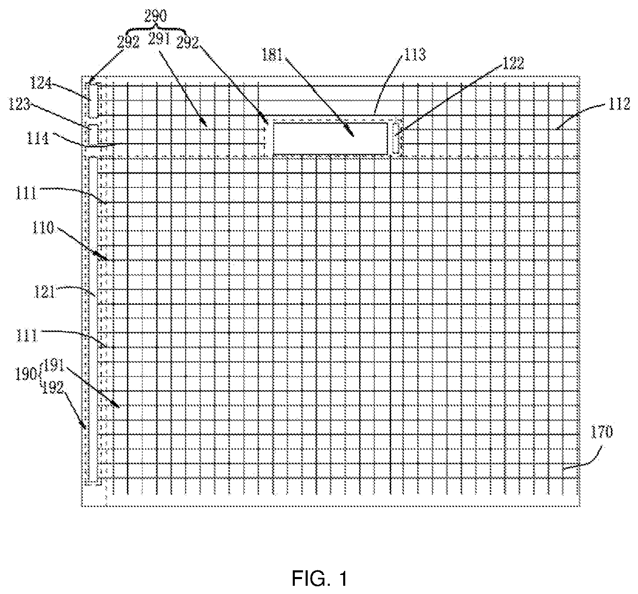
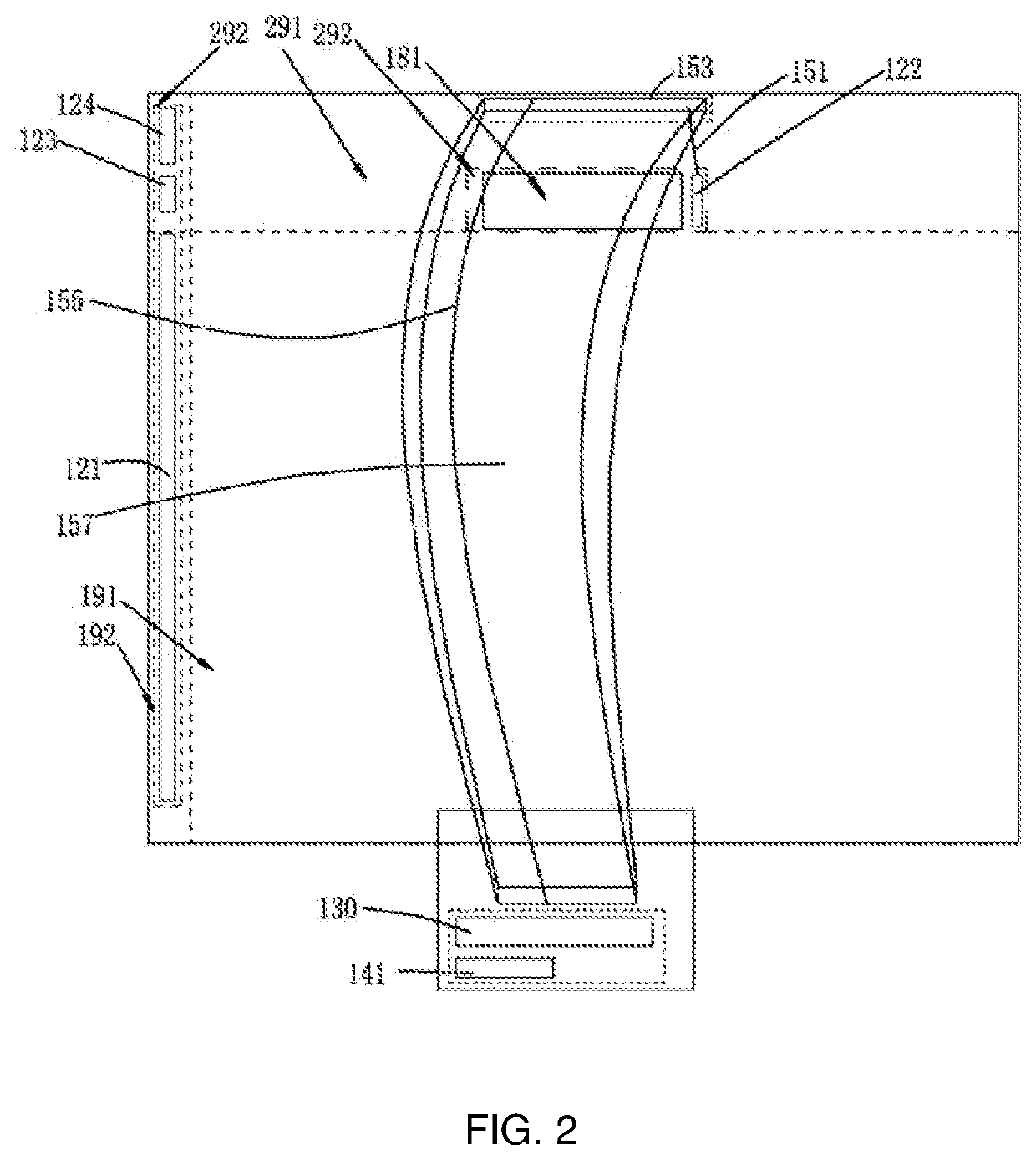
[0026]The embodiment of the present application provides a display panel. The display panel is used for display. The display panel can be applied to electronic products, such as mobile phones, tablet computers, and notebook computers. Referring to FIGS. 1 and 2, the display panel comprises a primary display area 190 and a secondary display area 290. The primary display area is provided with a first gate driving unit 121 for display driving. In this embodiment, the primary display area 190 comprises a primary area 191 and a primary device area 192. The primary area 191 is located in the middle of the primary display area 190 and is used for display. The primary device area 192 is located at the edge of the primary display area 190 and is not used for display, but used to, for example, accommodate the first gate driving unit 121. The secondary display area 290 is provided with a second gate driving unit 122 for display driving. In this embodiment, the secondary display area 290 compri...

second embodiment

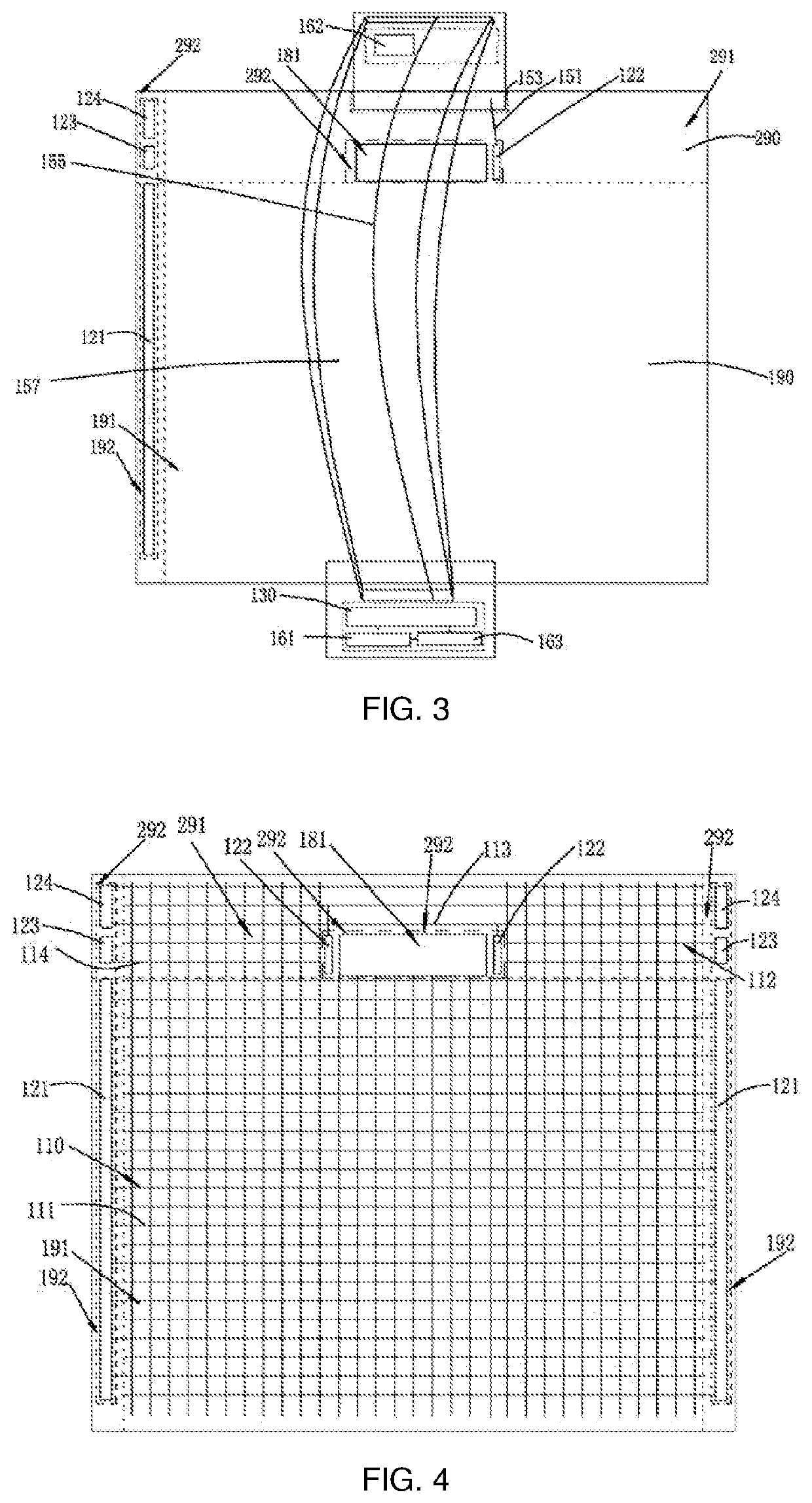
[0046]FIG. 4 is a schematic diagram of a display panel according to a second embodiment of the present application. The schematic diagram of FIG. 4 is similar to that of FIG. 1. Therefore, a same reference number represents the same component, which will not be repeated here. The main difference between this embodiment and the first embodiment is that the numbers of the first gate driving unit to the fourth gate driving unit are all two.

[0047]Referring to FIGS. 4 and 5, in this embodiment, the number of the first gate driving units 121 is two, wherein the two first gate driving units 121 are respectively located at the left edge and the right edge of the primary display area 190. The two first gate driving units 121 are both GOA circuits, and the two first gate driving units 121 are alternately connected to the first scanning lines 111 in sequence. Specifically, the first gate driving unit 121 on the left side is electrically connected to the first scanning lines 111 numbered as an ...

third embodiment

[0054]FIG. 6 is a schematic diagram of a display panel according to a third embodiment of the present application. The schematic diagram of FIG. 6 is similar to that of FIG. 1. Therefore, the same reference number indicates the same component, which will not repeated here. The main difference between this embodiment and the first embodiment is that the periphery (four sides) of the via hole is used for display.

[0055]Referring to FIGS. 6 and 7, in this embodiment, the data lines 370 comprise an isolated data line 372 and a normal data line 371. The normal data line 371 which is continuous and uninterrupted, extends from the lower side of the display panel to the upper side of the display panel. The isolated data line 372 extends from the lower side of the display panel to the upper side of the display panel, wherein the isolated data line is interrupted. Specifically, it is separated into two parts at the via hole 181. In this embodiment, the isolated data line 372 includes a first d...


PUM


Abstract

A display panel and a display comprising the display panel. The display panel comprises a primary display area (190) and a secondary display area (290); a first gate driving unit (121) for display driving is provided in the primary display area (190), and a second gate driving unit (122) for display driving is provided in the secondary display area (290); a via hole (181) is formed in the secondary display area (290); at least a portion of the secondary display area (290) is configured to display an image together with at least a portion of the primary display area (190). The display panel increases the screen-to-body ratio and is more attractive.

Description

TECHNICAL FIELD[0001]The present application relates to the technical field of display, in particular, to a display panel and a display.BACKGROUND ART[0002]On the current market, the screen-to-body ratio of display panels of mobile phone products becomes larger increasingly, with the larger screen-to-body ratio as a trend and fashion. However, due to consumers' function requirements for other aspects of a mobile phone, the front-end hardware, such as the front camera of a mobile phone, various light sensors, a depth-of-field infrared sensor, earpieces and the like on the front of a mobile phone, will occupy the display space of the screen, thereby reducing the screen-to-body ratio.[0003]In order to solve this contradiction, some mobile phones use display panels, such as, “bang screen”, “water drop screen” and so on. This design can increase the screen-to-body ratio of the display panel and leave room for applying various front-end hardware. However, such design is difficult to furth...

Claims


Application Information

Patent Timeline
Patent Type & Authority Applications(United States)
IPC IPC(8): H01L27/12
CPCH01L27/124G09G3/20G02F1/133
Inventor GUO, XINGLINGTAN, XIAOPINGLIU, XING
Owner SHENZHEN ROYOLE TECH CO LTD
Why Eureka
Try Eureka