
Detector

a detector and detector technology, applied in the field of detectors, can solve the problems of ineffective methods and the possibility of severe injuries of the occupants of such containers, and achieve the effects of reducing the shock/impact of the container, reducing the impact damage, and increasing the service life of the detector

Pending Publication Date: 2022-04-21
TOTAL WASTE SOLUTIONS LTD
View PDF0 Cites 0 Cited by
  • Summary
  • Abstract
  • Description
  • Claims
  • Application Information

AI Technical Summary

Benefits of technology

The housing of the detector is sealed to prevent dust and water from entering and interfering with its function. A fire suppressant device prevents fire from spreading and causing harm. As a result, the detector can function safely and efficiently without being affected by environmental factors.

Problems solved by technology

It is possible for occupants of such a container to be severely injured, e.g. if they are transferred from the container to a refuse / recycling compacting collection vehicle.
However, these methods are not always effective, e.g. if a person within a container does not wake up, or is not visible to an operator.

Method used


Image

  • Detector
  • Detector
  • Detector

Examples


Embodiment Construction

)

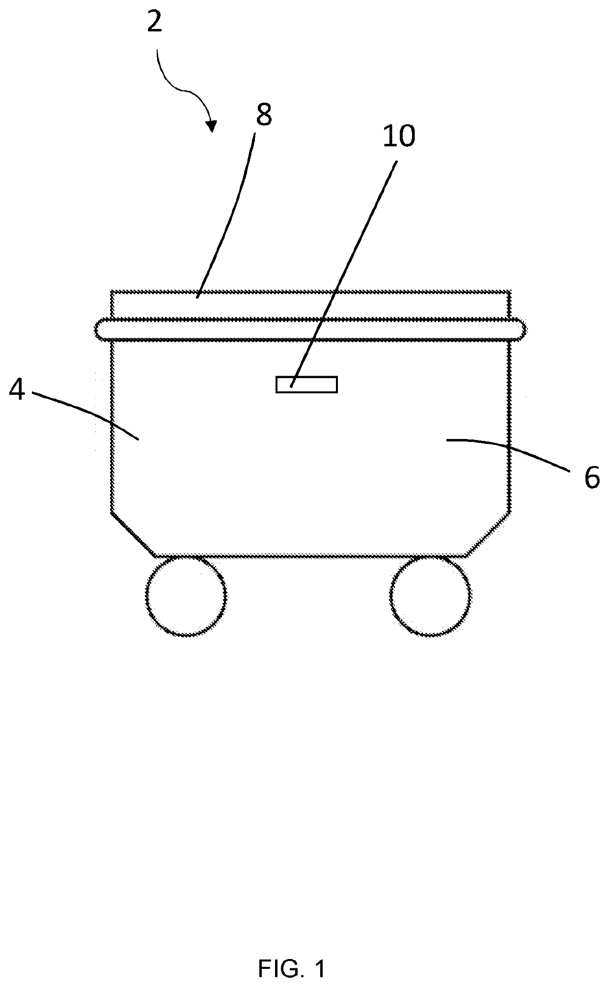
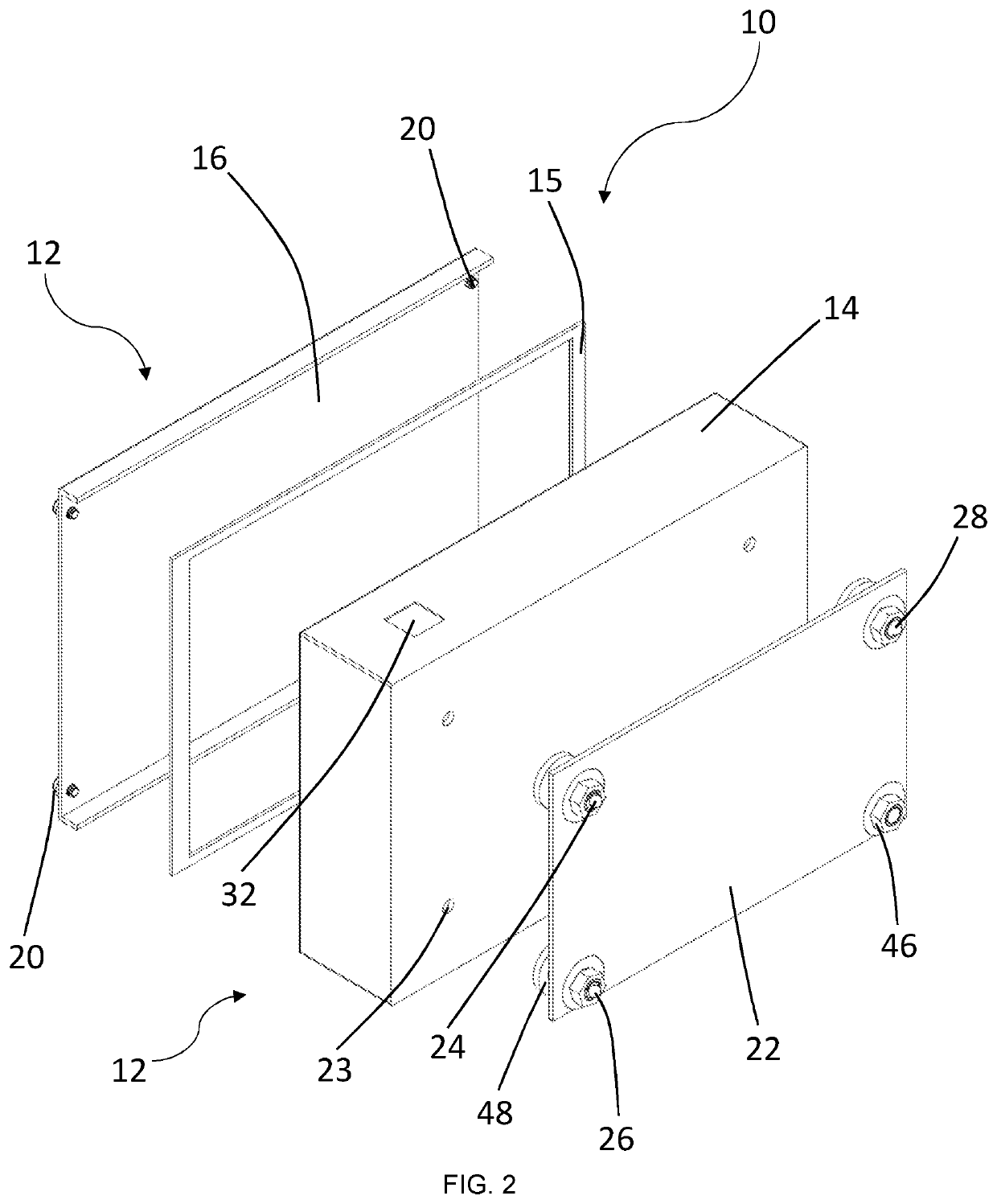
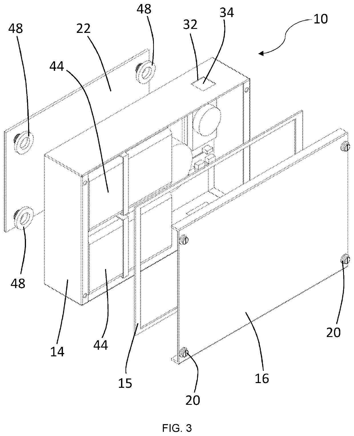
[0102]Referring to FIG. 1, a detector 10 is illustrated mounted to a container 2. The container 2 includes a body 4 defining an internal / enclosed space 6 and a lid 8 for opening and closing the container 2. The detector 10 is partially positioned within the internal space 6 of the container 2 and is configured to be able to determine the occupancy within the container 2 (i.e. the detector is configured to determine whether one or more people are in the container 2).

[0103]The detector 10 is configured to monitor the occupancy of the container 2 by sensing the composition of the air within the container 2. In the arrangement shown, the container body 4 includes four side walls, and the detector 10 is mounted to one of said side walls of the container 2. The detector 10 positioned a distance approximately a third of the height of the container, below the upper edge of the container. This positioning has been found to provide accurate measurements, and positions the detector 10 away fr...


PUM


Abstract

A detector (10; 110) is provided for mounting to a container (2) defining an internal space (6) in order to determine occupancy of the container. The detector includes a housing (12; 112), a mounting arrangement for mounting the housing to a container, a sensor arrangement comprising a first sensor (30; 130) disposed within the housing, the first sensor configured to determine a concentration of carbon dioxide within an internal space (6) of a container (2); and a control system (40; 140) configured to receive input values from the first sensor and to provide an output when the concentration of carbon dioxide exceeds a predetermined value. The housing is substantially sealed for preventing the ingress of debris into the housing, and the housing is configured such that air is able to flow into the housing and over the first sensor.

Description

FIELD OF THE INVENTION[0001]The present invention relates to a detector for determining the occupancy of a container, and to a container including detector for determining the occupancy thereof.BACKGROUND OF THE INVENTION[0002]In order to find shelter from harsh weather conditions, it is becoming an increasingly common occurrence for people to find rest in a refuse or recycling container (also known as a bin). It is possible for occupants of such a container to be severely injured, e.g. if they are transferred from the container to a refuse / recycling compacting collection vehicle. In light of this, there is growing concern within the refuse / recycling collection industry about the rising number of people sleeping in such containers.[0003]In order to reduce the risk of an occupant of a container becoming injured, it is common practice for operators (i.e. refuse / recycling collectors) to try and determine the occupancy of a container prior to emptying the recycling / refuse in the contain...

Claims


Application Information

Patent Timeline
IPC IPC(8): G01N33/00B65F1/14G01N33/497
CPCG01N33/0063B65F1/14B65F2001/1692G01N33/0031B65F2210/168G01N33/497B65F2210/20G08B21/22G08B29/183G01N33/0009G01N33/004G08B21/02G08B29/12G08B5/36G08B3/00G08B5/00
Inventor SHARMAN, PAULBLAND, GRAHAMHALE, TIMOTHY
Owner TOTAL WASTE SOLUTIONS LTD
Learn More