Device for heating a vehicle cover

a technology for heating devices and vehicle covers, which is applied in the direction of vehicle cleaning, lighting and heating apparatus, instruments, etc., can solve the problems of window interference with lidar measurement, interference of radar signals, and interference with radar signals

Pending Publication Date: 2022-04-28
HELLA KG HUECK & CO
View PDF0 Cites 0 Cited by
  • Summary
  • Abstract
  • Description
  • Claims
  • Application Information

AI Technical Summary

Benefits of technology

[0006]It is therefore an object of the present invention to provide a device in which water or ice situated on a cover may b

Problems solved by technology

The condensation or the ice may interfere with the radar signals.
It has proven to be disadvantageous, in particular, that the heating wires reduce the permeability of electromagnetic radiatio

Method used


Image

  • Device for heating a vehicle cover

Examples


Embodiment Construction

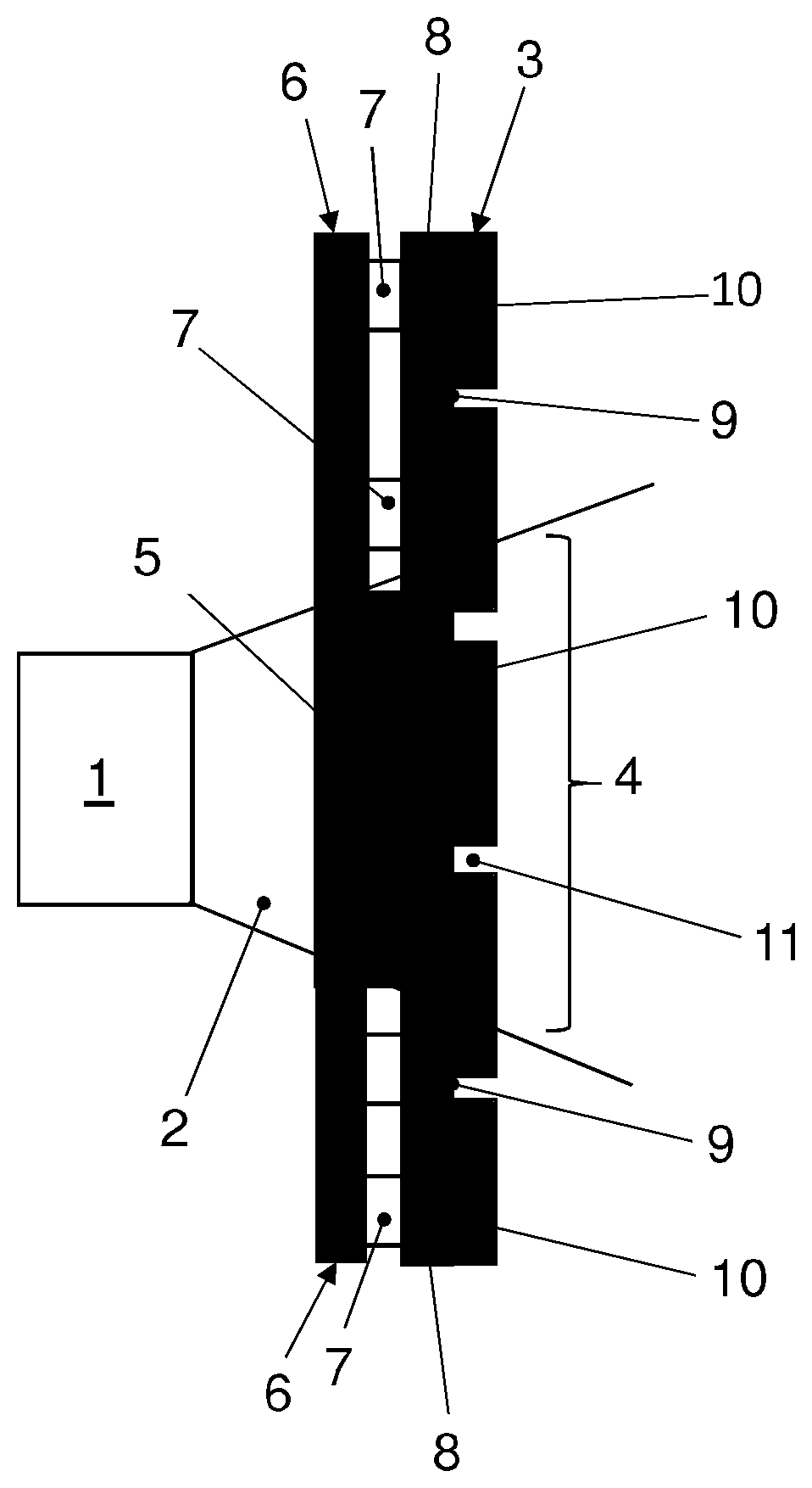
[0021]The specific embodiment of a device according to the invention illustrated in the figures used as a sensor device and comprises a sensor unit 1, which is designed, for example, as a radar unit. Sensor unit 1 may emit and / or receive electromagnetic radiation 2. Radiation 2 may be, for example, radiation in a wavelength range between 1 mm and 100 mm.

[0022]The device further comprises a housing, of which only front cover 3 is shown. Radiation 2 emitted by sensor unit 1 emerges from the housing through cover 3. The conical area, in particular the radar cone, in which radiation 2 diffuses, is indicated by reference numeral 4.

[0023]The device comprises a base plate 5, through which radiation 2 passes before it strikes cover 3. The base plate is surrounded by a circuit board 6, on which a plurality of light-emitted diodes 7 are arranged. Instead of a circuit board 6, multiple circuit boards 6 may also be provided. Instead of multiple light-emitting diodes 7, only one single light-emi...


PUM


Abstract

A device for a vehicle, comprising a cover, a source of electromagnetic heating radiation, which is used to heat the cover, as well as a light guide, through which the heating radiation emerging from the source of electromagnetic heating radiation is guided to the cover.

Description

[0001]This nonprovisional application is a continuation of International Application No. PCT / EP2020 / 067859, which was filed on Jun. 25, 2020, and which claims priority to German Patent Application No. 10 2019 117 968.8, which was filed in Germany on Jul. 3, 2019, and which are both herein incorporated by reference.BACKGROUND OF THE INVENTIONField of the Invention[0002]The present invention relates to a device for heating a cover of a vehicle.Description of the Background Art[0003]Sensor devices are becoming more and more important in vehicles. They are used, for example, for driver assistance systems or for automatic emergency brake systems. Sensor devices are generally installed in the front area of the vehicle or in the bumper. The sensor devices may be, for example, a radar sensor, which, for design reasons, is provided with a cover referred to as a radome. At low ambient temperatures, the cover may become covered with dew, or an ice layer may form on the cover. The condensation ...

Claims


Application Information

Patent Timeline
IPC IPC(8): F21S45/60H05B3/00G01S7/02G01S13/931B60S1/02
CPCF21S45/60H05B3/0042B60Q1/0005G01S13/931B60S1/026G01S7/027G01S17/95G01S17/58G01S17/931H05B3/84F21V29/90G01S2007/4977Y02A90/10
Inventor KUTTIKKATTIL, PRADEEPNDJEUNDOUN, PAUL ROSTANDWAGA, MARTIN METHA
Owner HELLA KG HUECK & CO
Why Eureka
Try Eureka