Rotary Shifter Assembly

a technology of rotary shifters and assembly parts, which is applied in the direction of gearing control, gearing elements, and gearing control, etc., can solve the problems of extreme torque applied to the gear shifter by the user, inoperability failure of one or more parts of the shifter assembly, so as to reduce the instances of parts breaking and failure, and improve the functionality and usability

Pending Publication Date: 2022-05-05
KA GRP AG
View PDF4 Cites 2 Cited by
  • Summary
  • Abstract
  • Description
  • Claims
  • Application Information

AI Technical Summary

Benefits of technology

[0011]In this way, the shifter assembly of the present invention provides improved functionality and usability in connection with automatic transmission systems and, at the same time, reduces instances of parts breakage and failure.

Problems solved by technology

There are some disadvantages with respect to using known electronic shifter assemblies due to operator error.
One such disadvantage occurs when extreme torque is applied to the gear shifter by the user, which can occur, for example, when one of the parts of the shifter assembly is stuck or otherwise not operating properly.
The user attempts to shift the gears using the shifter and over-rotates the shifter when the desired gear is not achieved.
This can result in inoperability of the shifter assembly or even breakage of one or more of the parts of the shifter assembly.
The inability of a user (e.g., a driver of the vehicle) to operate the shifter assembly or drive the vehicle may result in endangerment of the user.

Method used


Image

  • Rotary Shifter Assembly
  • Rotary Shifter Assembly
  • Rotary Shifter Assembly

Examples


Embodiment Construction

[0028]Referring now to the drawings, wherein like numerals indicate corresponding parts throughout the several views, embodiments of a rotary shifter assembly or shifter unit are shown throughout the figures and described in detail below.

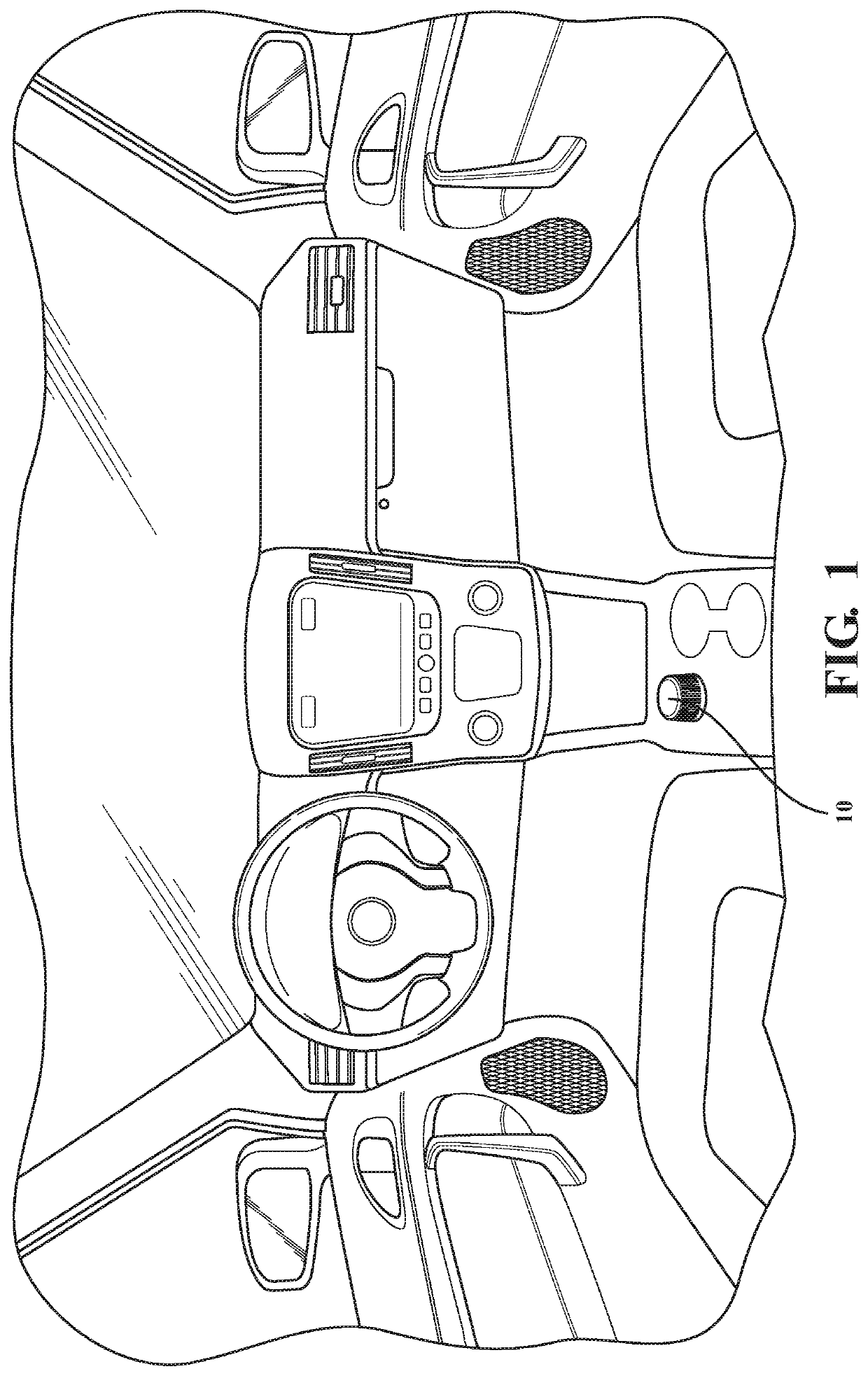
[0029]Referring now to FIG. 1, a perspective view of an interior of a vehicle including a rotary shifter assembly or shifter unit is shown. A shift knob 10 is exposed within a passenger compartment of a vehicle and is usable by a vehicle operator to actuate movement of the rotary shifter assembly 14 to a desired gear change for controlling a vehicle transmission system.

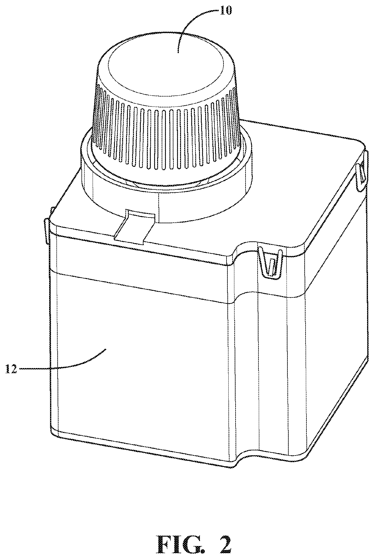
[0030]Referring now to FIG. 2, a perspective view of a housing according to one embodiment of the present invention is shown. The housing 12 supports the shift knob 10 coupled to the rotary shifter assembly 14. The rotary shifter assembly 14 is partially contained within the housing 12.

[0031]The rotary shifter assembly 14 may be used for changing gears of a vehicle transmission system...


PUM


Abstract

A rotary shifter assembly for changing gears in a vehicle transmission includes a shaft (16) that is rotatably supported in a housing (12) and movable between radial positions for indicating a gear change. A shift knob (10) is coupled to a first end of the shaft for actuation by a user. A plurality of flexible locking fingers (40) extend from the second end, and an overload wheel (18) is disposed about the fingers. The fingers engage the wheel to couple it with the shaft for concurrent rotation. A locking mechanism (64) engages the wheel to selectively prevent and allow concurrent rotation of the wheel and shaft during normal operation. The fingers move relative to the wheel to permit temporary rotation of the shaft relative to the wheel when a force applied to the shaft is beyond a maximum torque threshold, and automatically return to concurrent rotation with the wheel once the force is below the threshold.

Description

CROSS-REFERENCE TO RELATED APPLICATION[0001]This application claims the benefit of U.S. Provisional Patent Application No. 62 / 795,081, filed Jan. 22, 2019, which is hereby incorporated by reference in its entirety.BACKGROUND OF THE INVENTION1. Field of the Invention[0002]The present disclosure relates generally to rotary shifter assemblies.2. Description of the Related Art[0003]Conventional automotive powertrain systems known in the art include an engine in rotational communication with a transmission. The engine generates rotational torque which is selectively translated to the transmission which, in turn, translates rotational torque to one or more wheels to drive a vehicle. The transmission multiplies the rotational speed and torque generated by the engine through a series of predetermined gear sets, whereby changing between gear sets enables the vehicle to travel at different vehicle speeds for a given engine speed. Thus, the gear sets of the transmission are configured such tha...

Claims


Application Information

Patent Timeline
Patent Type & Authority Applications(United States)
IPC IPC(8): F16D43/202F16H59/02F16H59/08
CPCF16D43/2028F16H2059/081F16H59/08F16H59/0217F16H59/04F16H61/22F16H2059/0282F16H2059/083F16D43/202
Inventor BLANK, DAVID
Owner KA GRP AG
Why Eureka
Try Eureka