
Convenient and stable mechanical part fixing device

A technology of mechanical parts and fixing devices, which is applied in the direction of metal processing mechanical parts, positioning devices, clamping, etc., can solve problems that affect machine movement and cutting accuracy, jumping parts, injuries, etc., to increase functionality and practicability Effect

Inactive Publication Date: 2021-04-13
宁波吉鑫机械制造有限公司
View PDF11 Cites 0 Cited by
  • Summary
  • Abstract
  • Description
  • Claims
  • Application Information

AI Technical Summary

Problems solved by technology

[0002] Mechanical parts are the basic components of machinery, and they are inseparable individual parts that make up machinery and machines. The use of left-shift mechanical parts is very wide, but the same, because some mechanical parts are relatively small in size and shape Irregularity, so in terms of fixing, it is difficult to fix it firmly and conveniently, and the current part fixing devices are directly clamping it, and there is no flexibility at all. Such a strong clamping will damage the beetle clamping device. The pressure will damage the device for a long time, and when the shape of the part is irregular, the part will be separated from the device when the part is clamped vigorously, so that the part will fly and cause unpredictable damage. During the cutting process, a large amount of metal waste will be generated. These wastes will splash around due to the collision between the cutting edge and the parts, thus attaching to the machine and even entering the inside of the machine, thereby shortening the service life of the machine and causing Affects the accuracy of machine movement and cutting

Method used


Image

  • Convenient and stable mechanical part fixing device
  • Convenient and stable mechanical part fixing device
  • Convenient and stable mechanical part fixing device

Examples


Embodiment Construction

[0020] The following will clearly and completely describe the technical solutions in the embodiments of the present invention with reference to the accompanying drawings in the embodiments of the present invention. Obviously, the described embodiments are only some, not all, embodiments of the present invention. Based on the embodiments of the present invention, all other embodiments obtained by persons of ordinary skill in the art without making creative efforts belong to the protection scope of the present invention.

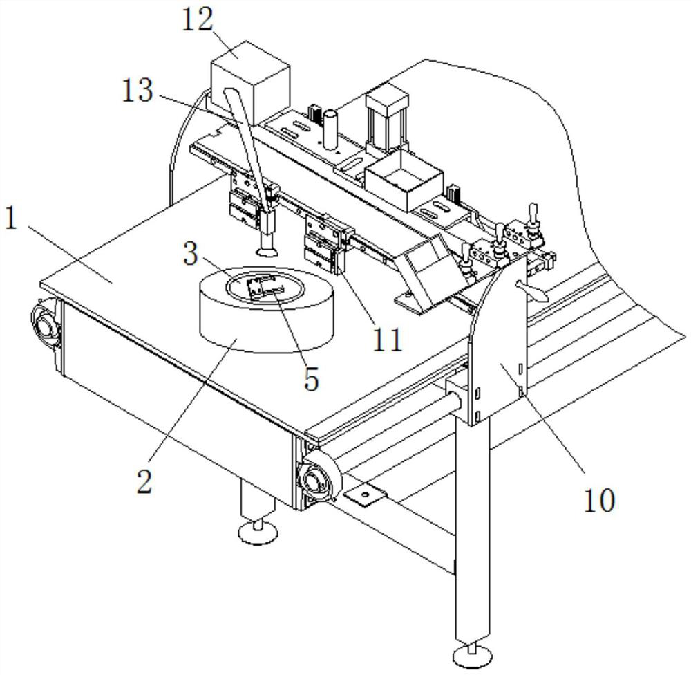
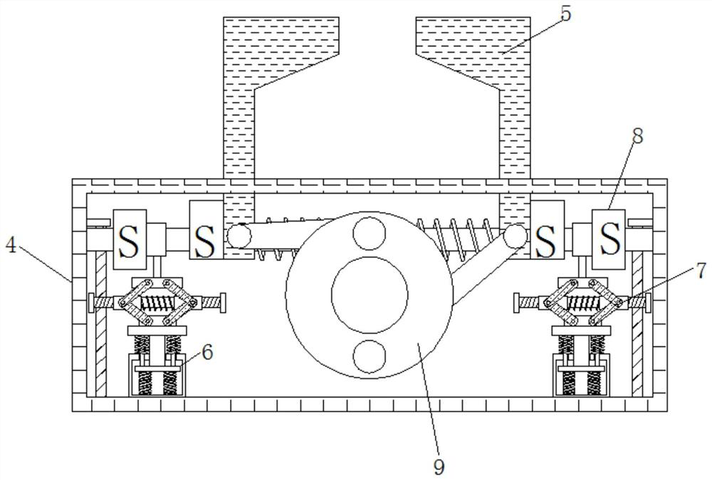
[0021] see Figure 1-4 , a convenient and stable mechanical parts fixing device, comprising a base 1, the top of the base 1 is fixedly connected with a base 2, the inside of the base 2 is rotatably connected with a rotating block 3, and the top of the rotating block 3 is fixedly connected with a fixed block 4, the fixed block The inside of 4 is slidingly connected with a clamping block 5, and the bottom inner wall of the fixed block 4 is slidably connected wit...


PUM


Abstract

The invention relates to the technical field of mechanical design part manufacturing, and discloses a convenient and stable mechanical part fixing device which comprises a foundation base, wherein a base is fixedly connected to the top end of the foundation base, a rotating block is rotatably connected to the interior of the base, and a fixing block is fixedly connected to the top end of the rotating block; a clamping block is slidably connected into the fixing block, a sliding frame is slidably connected to the inner wall of the bottom end of the fixing block, a rotating rod is rotatably connected to the top end of the sliding frame, a magnet is fixedly connected to the surface of the bottom end of the clamping block, and a first rotating disc is rotatably connected into the fixing block; and the side surface of the foundation base is slidably connected to a sliding plate. A clamping block moving device is formed by arranging the first rotating disc, the clamping block, the magnet, the sliding frame and the spring, clamping of the clamping block has elasticity, in this way, a part can be stably clamped, the part and the device cannot be damaged, and the functionality and practicability of the device are improved.

Description

technical field [0001] The invention relates to the technical field of manufacturing mechanical design parts, in particular to a convenient and stable fixing device for mechanical parts. Background technique [0002] Mechanical parts are the basic components of machinery, and they are inseparable individual parts that make up machinery and machines. The use of left-shift mechanical parts is very wide, but the same, because some mechanical parts are relatively small in size and shape Irregularity, so in terms of fixing, it is difficult to fix it firmly and conveniently, and the current part fixing devices are directly clamping it, and there is no flexibility at all. Such a strong clamping will damage the beetle clamping device. The pressure will damage the device for a long time, and when the shape of the part is irregular, the part will be separated from the device when the part is clamped vigorously, so that the part will fly and cause unpredictable damage. During the cutt...

Claims


Application Information

Patent Timeline
IPC IPC(8): B23Q3/06B23Q11/00
CPCB23Q3/06B23Q11/0042
Inventor 蒋海东
Owner 宁波吉鑫机械制造有限公司
Learn More