Permeable support layer for fuel cell fluid flow networks

Pending Publication Date: 2022-05-05
TOYOTA MOTOR ENGINEERING & MANUFACTURING NORTH AMERICA
View PDF2 Cites 0 Cited by
  • Summary
  • Abstract
  • Description
  • Claims
  • Application Information

AI Technical Summary

Benefits of technology

The patent text describes a strategic placement of a permeable support layer between an air plate and a hydrogen plate in a fuel cell to prevent flow blockage and improve thermal management. The permeable support layer allows for a consistent path for coolant flow and enables improved performance and efficiency of the fuel cell.

Problems solved by technology

This may, in turn, reduce the coolant flow within the coolant layer, which adversely effects the performance of the FC.
In some regions, however, the coolant microchannels are very narrow or completely blocked, while in other regions the coolant microchannels are wide and open.
This may lead to non-uniform thermal management throughout the FC stack, and consequently, inefficient FC stack performance.

Method used


Image

  • Permeable support layer for fuel cell fluid flow networks
  • Permeable support layer for fuel cell fluid flow networks
  • Permeable support layer for fuel cell fluid flow networks

Examples


Embodiment Construction

[0023]As illustrated in FIGS. 1 and 2, a fuel cell 10 comprises a first bipolar plate defining an air layer 11, a second bipolar plate defining a hydrogen layer 12. The air layer 11 comprises a plurality of independently formed air fluid flow network or microchannels 11a, and the hydrogen layer 12 comprises a plurality of independently formed hydrogen fluid flow network or microchannels 12a. Through the superimposition or stacking of the air plate 11 and the hydrogen plate 12, a coolant layer 13 comprising a plurality of coolant flow network or microchannels 13a is defined. In this way, the coolant fluid flow network or microchannel configuration 13a is dependent upon the independently-formed air microchannels 11a and hydrogen microchannels 12a.

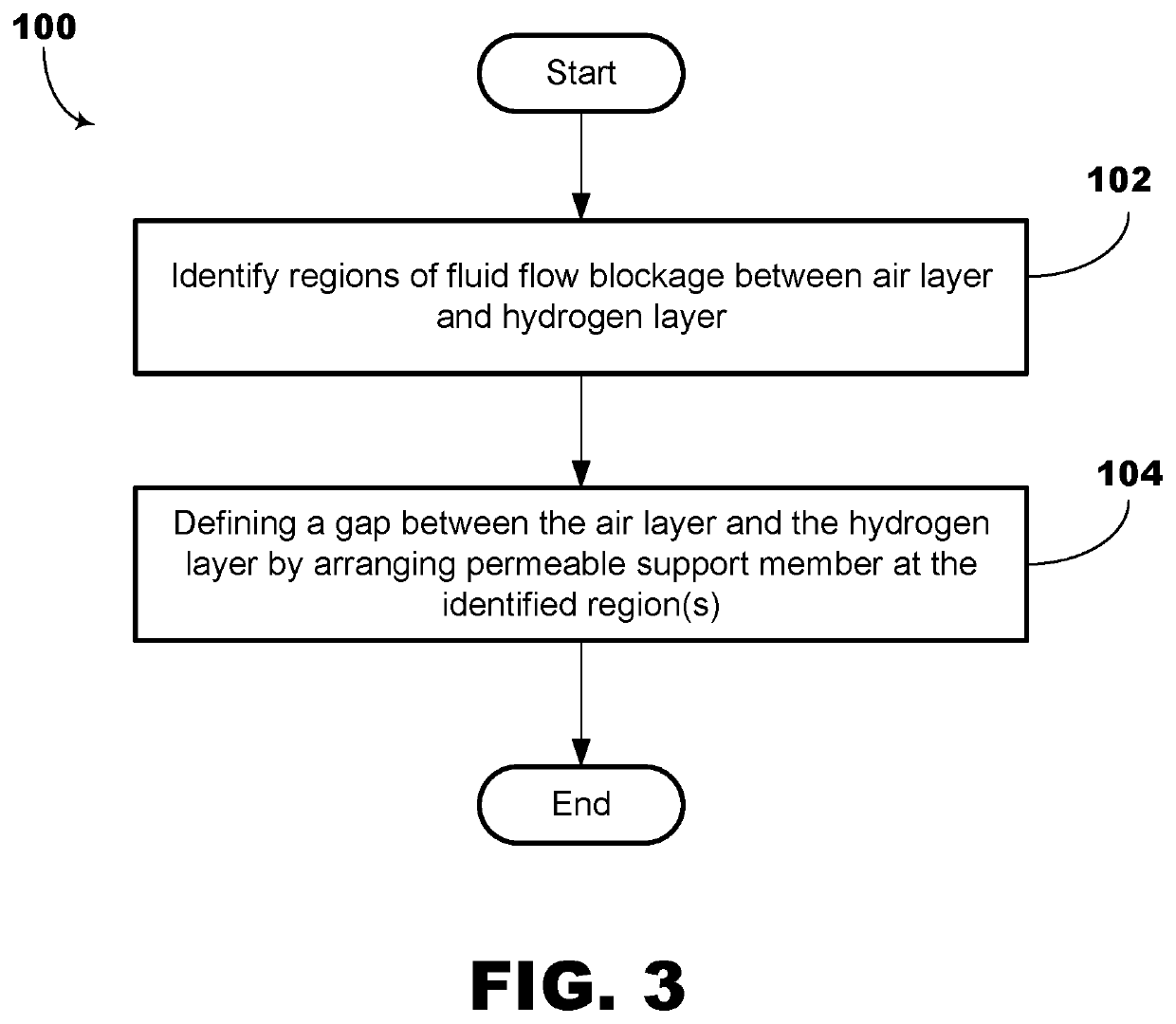
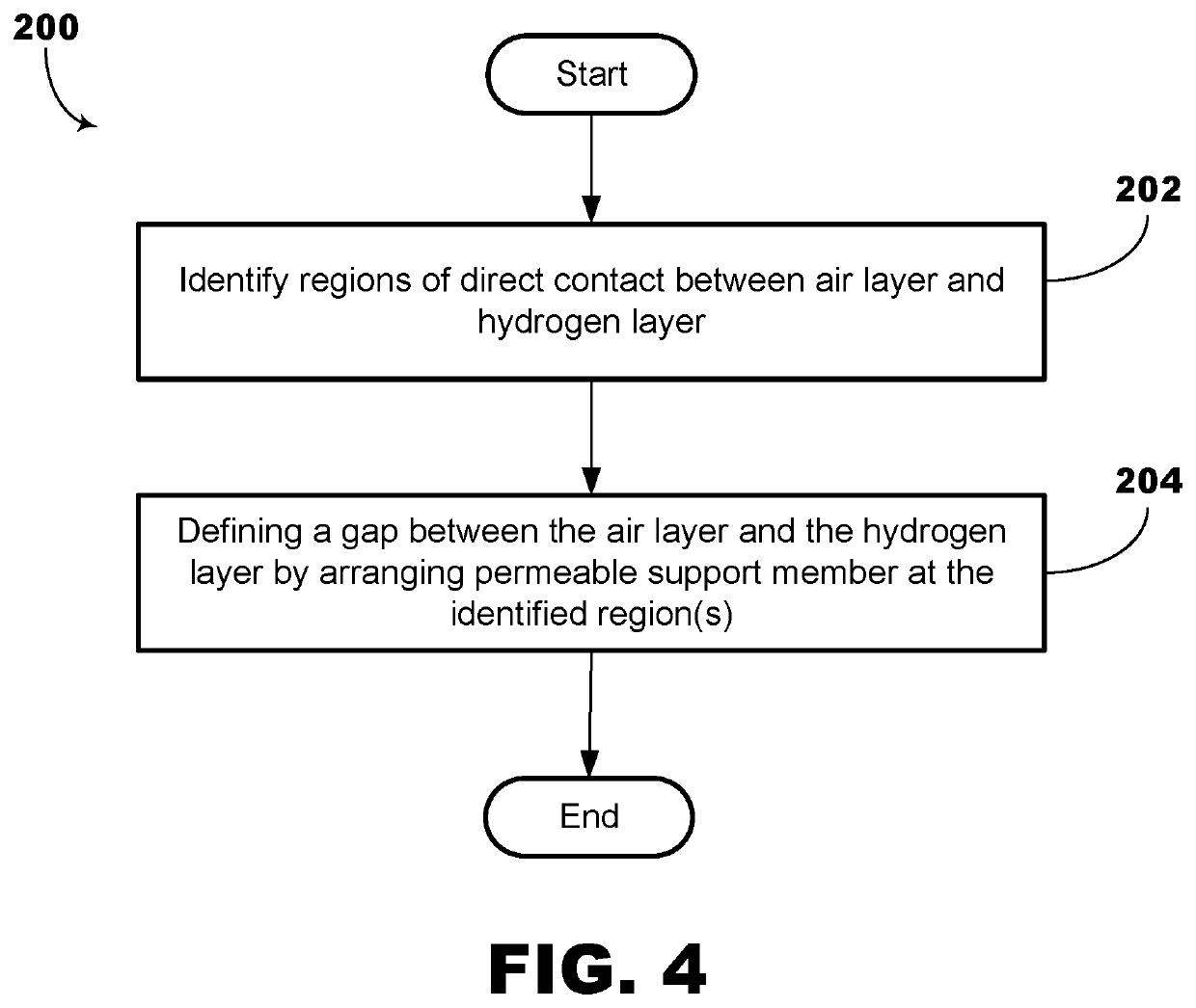
[0024]In accordance with one or more embodiments, to prevent blockage in the coolant microchannels 13a, particularly in regions or interfaces where there is direct contact between the air plate 11 and the hydrogen plate 12, a very thin perme...


PUM


Abstract

A fuel cell may include a first fuel cell bipolar plate defining an air layer, a second fuel cell bipolar plate defining a hydrogen layer, and a coolant layer defined by the air layer and the hydrogen layer. The coolant layer includes a plurality of coolant microchannels that facilitate flow of a coolant. A permeable support layer is arranged between the air layer and the hydrogen layer to define a gap therebetween to prevent flow blockage of the coolant microchannels while facilitating coolant flow therethrough.

Description

TECHNICAL FIELD[0001]Embodiments relate generally to a fuel cell (FC), and one or more methods of fabricating an (FC).BACKGROUND[0002]Hydrogen fuel cell (FC) technology has been utilized widely in a variety of stationary and non-stationary applications, e.g., space transport, satellites, motor vehicles, power generation, and electronics. The FC device converts chemical potential energy into electrical energy.[0003]A FC stack generally comprises hundreds of FCs arranged in a stack formation. Each fuel cell comprises a hydrogen layer defined by a hydrogen plate having a plurality of channels for facilitating hydrogen flow into a reaction zone, an air layer defined by an air plate having a plurality of channels for facilitating air flow into the reaction zone, and a coolant layer defined by superposition or stacking of the hydrogen plate on the air plate. The hydrogen plate and the air plate may be fabricated by a stamping process to provide the plurality of channels.[0004]The MEA is a...

Claims


Application Information

Patent Timeline
IPC IPC(8): H01M8/0258H01M8/0232H01M8/0228H01M8/0267
CPCH01M8/0258H01M8/0267H01M8/0228H01M8/0232H01M8/0254H01M8/0223Y02E60/50
Inventor DEDE, ERCAN M.ZHOU, YUQING
Owner TOYOTA MOTOR ENGINEERING & MANUFACTURING NORTH AMERICA
Why Eureka
Try Eureka