Thermoelectric-enhanced, inlet air cooling for an electronics rack

a technology of inlet air cooling and electronics racks, which is applied in the direction of electrical equipment, electrical apparatus, electrical apparatus contruction details, etc., can solve the problems of difficult cooling and approach, and achieve the effect of convenient cooling, convenient cooling, and convenient cooling

Active Publication Date: 2017-01-12
IBM CORP
View PDF0 Cites 16 Cited by
  • Summary
  • Abstract
  • Description
  • Claims
  • Application Information

AI Technical Summary

Benefits of technology

[0003]In one or more aspects, the shortcomings of the prior art are overcome and additional advantages are provided through the provision of a cooling apparatus which comprises an air-to-liquid heat exchanger, a coolant loop, a heat rejection unit, and at least one thermoelectric heat pump. The air-to-liquid heat exchanger is associated with an electronics rack and disposed at an air-inlet side of the electronics rack, wherein an airflow enters the electronics rack at the air-inlet side and egresses from the electronics rack at an air-outlet side, and the air-to-liquid heat exchanger cools, at least in part, the airflow into the electronics rack. The coolant loop facilitates coolant flow through air-to-liquid heat exchanger, and includes a first loop portion and a second loop portion. The air-to-liquid heat exchanger exhausts heated coolant to the first loop portion and receives cooled coolant from the second loop portion. The heat rejection unit is coupled to the coolant loop between the first loop portion and the second loop portion, and rejects heat from the heated coolant passing through the first loop portion to provide partially-cooled coolant to the second loop portion. The at least one thermoelectric heat pump is disposed with the first loop portion of the coolant loop coupled to a first side of the at least one thermoelectric heat pump, and the second loop portion of the coolant loop coupled to a second side of the at least one thermoelectric heat pump. The at least one thermoelectric heat pump transfers heat from the partially-cooled coolant within the second loop portion to the heated coolant within the first loop portion to provide the cooled coolant for the air-to-liquid heat exchanger.
[0004]In another aspect, a data center is provided which includes multiple electronics racks and a cooling apparatus for cooling an electronics rack of the multiple electronics racks. The cooling apparatus includes an air-to-liquid heat exchanger, a coolant loop, a heat rejection unit, and at least one thermoelectric heat pump. The air-to-liquid heat exchanger is associated with the electronics rack and disposed at an air-inlet side of the electronics rack, wherein an airflow enters the electronics rack at the air-inlet side and egresses from the electronics rack at an air-outlet side, and the air-to-heat liquid exchanger cools, at least in part, the airflow into the electronics rack. The coolant loop facilitates coolant flow through the air-to-liquid heat exchanger, and includes a first loop portion and a second loop portion. The air-to-liquid heat exchanger exhausts heated coolant to the first loop portion and receives cooled coolant from the second loop portion. The rejection unit is coupled to the coolant loop between the first loop portion and the second loop portion, and rejects heat from the heated coolant passing through the first loop portion to provide partially cooled coolant to the second loop portion. The at least one thermoelectric heat pump is disposed with the first loop portion of the coolant loop coupled to a first side of the at least one thermoelectric heat pump, and the second loop portion of the coolant loop coupled to a second side of the at least one thermoelectric heat pump. The at least one thermoelectric heat pump transfers heat from the partially cooled coolant within the second loop portion to the heated coolant within the first loop portion to provide the cooled coolant for the air-to-liquid heat exchanger.
[0005]In a further aspect, a method is provided which includes selectively providing rack level cooling of an airflow entering an air-inlet side of an electronics rack to facilitate cooling one or more electronic components of the electronics rack. The selectively providing includes: providing an air-to-liquid heat exchanger in association with the electronics rack, disposed at the air-inlet side of the electronics rack, the air-to-liquid heat exchanger extracting heat from the airflow entering the electronics rack and dissipating the heat to coolant passing through the air-to-liquid heat exchanger; coupling a coolant loop to the air-to-liquid heat exchanger, the coolant loop comprising a first loop portion and a second loop portion, the air-to-liquid heat exchanger exhausting heated coolant to the first loop portion and receiving cooled coolant from the second loop portion; providing a heat rejection unit coupled to the coolant loop between the first loop portion and the second loop portion, the heat rejection unit rejecting heat from the heated coolant passing through the first loop portion to provide partially cooled coolant to the second loop portion; and providing at least one thermoelectric heat pump disposed with the first loop portion of the coolant loop coupled to a first side of the at least one thermoelectric heat pump, and the second loop portion of the coolant loop coupled to a second side of the at least one thermoelectric heat pump, wherein the at least one thermoelectric heat pump transfers heat from the partially cooled coolant within the second loop portion to the heated coolant within the first loop portion to provide the cooled coolant for the air-to-liquid heat exchanger.

Problems solved by technology

This trend poses a cooling challenge at both module and system levels.
However, this approach may be problematic at the rack-level dependent, in part, on the inlet air temperature.

Method used


Image

  • Thermoelectric-enhanced, inlet air cooling for an electronics rack
  • Thermoelectric-enhanced, inlet air cooling for an electronics rack
  • Thermoelectric-enhanced, inlet air cooling for an electronics rack

Examples


Embodiment Construction

[0018]In a conventional air-cooled data center, multiple electronics racks may be disposed in one or more rows, with the data center housing several hundred, or even several thousand, microprocessors within the electronics racks. Note that “electronics rack”, “rack unit”, “rack”, “information technology (IT) rack”, etc., may be used interchangeably herein, and unless otherwise specified, include any housing, frame, support, structure, compartment, etc., having one or more heat-generating components of a computer system, electronic system, IT system, etc.

[0019]Note further that reference is made below to the drawings, which are not drawn to scale for ease of understanding of the various aspects of the present invention, wherein the same reference numbers used throughout different figures designate the same or similar components.

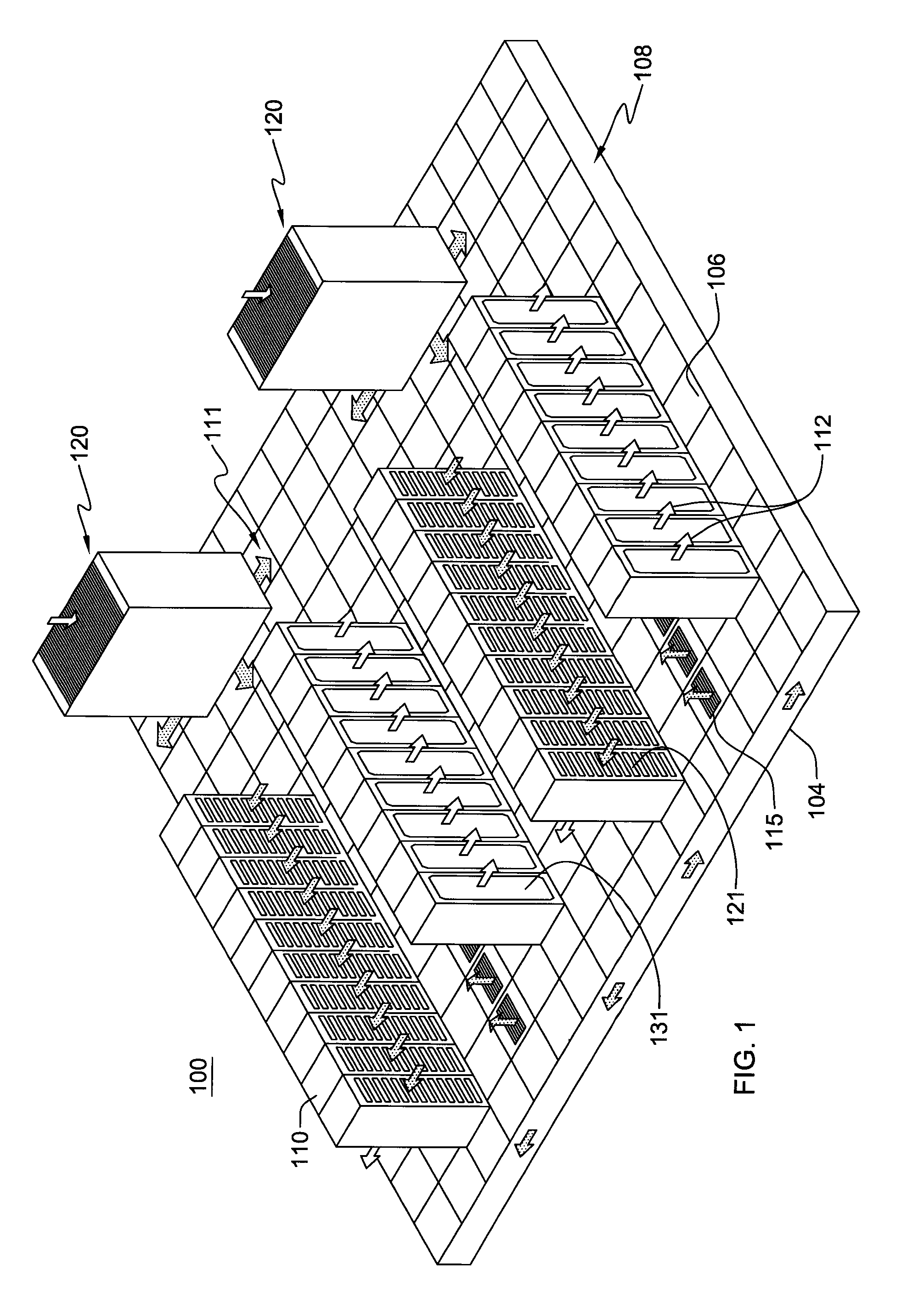
[0020]FIG. 1 depicts one embodiment of a data center 100, which in one example, is a raised floor layout of an air-cooled computer installation or data center...


PUM


Abstract

Thermoelectric-enhanced, rack-level cooling of airflow entering an electronics rack is provided by a cooling apparatus, which includes: an air-to-liquid heat exchanger; a coolant loop coupled to the heat exchanger, the coolant loop including a first loop portion and a second loop portion, where the heat exchanger exhausts heated coolant to the first loop portion and receives cooled coolant from the second loop portion. The cooling apparatus further includes a heat rejection unit and a thermoelectric heat pump(s). The heat rejection unit is coupled to the coolant loop between the first and second loop portions, and provides partially-cooled coolant to the second loop portion. The thermoelectric heat pump is disposed with the first and second loop portions coupled to opposite sides to transfer heat from the partially-cooled coolant within the second loop portion to provide the cooled coolant before entering the air-to-liquid heat exchanger.

Description

BACKGROUND[0001]The power dissipation of integrated circuit chips, and the modules containing the chips, continues to increase in order to achieve increases in processor performance. This trend poses a cooling challenge at both module and system levels. Increased airflow rates are needed to effectively cool high-power modules, and to limit the temperature of the air that is exhausted into the computer center.[0002]In many large server applications, processors, along with their associated electronics (e.g., memory, disk drives, power supplies, etc.), are packaged in removable node or drawer configurations stacked within an electronics (or IT) rack or frame. In other cases, the electronics may be in fixed locations within the rack or frame. Typically, the components are cooled by air moving in parallel airflow paths, usually front-to-back, impelled by one or more air-moving devices (e.g., axial or centrifugal fans). In some cases, it may be possible to handle increased power dissipati...

Claims


Application Information

Patent Timeline
Patent Type & Authority Applications(United States)
IPC IPC(8): H05K7/20
CPCH05K7/20781H05K7/20836H05K7/20736
Inventor CAMPBELL, LEVI A.DAVID, MILNES P.DEMETRIOU, DUSTIN W.ELLSWORTH, JR., MICHAEL J.SCHMIDT, ROGER R.SIMONS, ROBERT E.
Owner IBM CORP
Why Eureka
Try Eureka