Multi-component electronic module with integral coolant-cooling

a technology of electronic modules and components, applied in the direction of instruments, lighting and heating apparatus, and semiconductor/solid-state device details, to achieve the effect of facilitating coolant flow, facilitating coolant flow, and facilitating coolant flow

Inactive Publication Date: 2014-09-11
IBM CORP
View PDF7 Cites 16 Cited by
  • Summary
  • Abstract
  • Description
  • Claims
  • Application Information

AI Technical Summary

Benefits of technology

[0003]The shortcomings of the prior art are addressed and additional advantages are provided through the provision of a coolant-cooled electronic module which includes: a multi-component assembly; a module lid assembly; an inner manifold element; and an outer manifold element. The multi-component assembly includes multiple electronic components to be cooled disposed on a substrate, and the module lid assembly includes a module lid and multiple thermally conductive elements. The module lid comprises multiple openings through the module lid aligned over the multiple electronic components of the multi-component assembly, and the multiple thermally conductive elements are disposed within the multiple openings in the module lid. One thermally conductive element of the multiple thermally conductive elements includes opposite coolant-cooled and conduction surfaces, with the conduction surface being thermally coupled via a thermal conduction path to one electronic component of the multiple electronic components of the multi-component assembly. The inner manifold element is disposed over the lid assembly and includes first and second opposing main surfaces, with the first main surface being configured to facilitate flow of coolant onto, at least in part, the coolant-cooled surface of the one thermally conductive element, and including a coolant supply opening disposed over the coolant-cooled surface of the one thermally conductive element, and a coolant exhaust channel disposed, at least in part, adjacent to the coolant-cooled surface of the one thermally conductive element. The outer manifold element is disposed over the inner manifold element and coupled to the module lid, with the inner manifold element disposed between the outer manifold element and the module lid. The inner manifold element and the outer manifold element together define, at least in part, a coolant supply manifold over the second main surface of the inner manifold element, and the outer manifold element and the module lid together define, at least in part, a coolant return manifold. The coolant supply opening is in fluid communication with the coolant supply manifold, and the coolant exhaust channel is in fluid communication with the coolant return manifold, and the coolant supply manifold, coolant supply opening, coolant exhaust channel, and coolant return manifold facilitate flow of coolant across the coolant-cooled surface of the one thermally conductive element.
[0004]In another aspect, a coolant-cooled electronic module is provided which includes: a multi-component assembly; a module lid assembly; an inner manifold element; and an outer manifold element. The multi-component assembly includes multiple electronic components disposed on a substrate, and the module lid assembly includes a module lid and multiple thermally conductive elements. The module lid comprises multiple openings through the module lid aligned over the multiple electronic components of the multi-component assembly, and the multiple thermally conductive elements are disposed within the multiple openings in the module lid. Each thermally conductive element of the multiple thermally conductive elements includes opposite coolant-cooled and conduction surfaces, with the conduction surface being thermally coupled to a respective electronic component of the multiple electronic components of the multi-component assembly. The inner manifold element is disposed over the lid assembly and includes first and second opposing main surfaces, with the first main surface being configured to facilitate flow of coolant onto the coolant-cooled surfaces of the multiple thermally conductive elements, and includes multiple coolant supply openings and multiple coolant exhaust channels, each coolant supply opening being disposed over, and each coolant exhaust channel being disposed, at least in part, adjacent to, the coolant-cooled surface of a respective thermally conductive element. The outer manifold element is disposed over the inner manifold element and coupled to the module lid, with the inner manifold element between the outer manifold element and the module lid. The inner manifold element and the outer manifold element define, at least in part, a coolant supply manifold over the second main surface of the inner manifold element, and the outer manifold and the module lid define, at least in part, a coolant return manifold. Each coolant supply opening is in fluid communication with the coolant supply manifold, and each coolant exhaust channel is in fluid communication with the coolant return manifold. The coolant supply manifold, multiple coolant supply openings, multiple coolant exhaust channels, and coolant return manifold facilitate coolant flow across the coolant-cooled surfaces of the multiple thermally conductive elements.
[0005]In a further aspect, a method is provided which includes: providing a coolant-cooled electronic module. The providing of the coolant-cooled electronic module includes: providing a multi-component assembly comprising multiple electronic components disposed on a substrate; providing a module lid assembly, the module lid assembly comprising: a module lid including multiple openings through the module lid aligned over the multiple electronic components of the multi-component assembly; and multiple thermally conductive elements disposed within the multiple openings in module lid, one thermally conductive element of the multiple thermally conductive elements comprising a coolant-cooled surface and a conduction surface, the coolant-cooled surface and the conduction surface being opposite surfaces of the one thermally conductive element, the conduction surface being thermally coupled via a thermal conduction path to one electronic component of the multiple electronic components of the multi-component assembly; and providing a manifold assembly configured to facilitate coolant flow across the coolant-cooled surface of the one thermally conductive element. The manifold assembly includes: an inner manifold element disposed over the lid assembly, the inner manifold element comprising opposite first and second main surfaces, the first main surface being configured to facilitate flow of coolant onto, at least in part, the coolant-cooled surface of the one thermally conductive element, and including a coolant supply opening disposed over the coolant-cooled surface of the one thermally conductive element, and a coolant exhaust channel disposed, at least in part, adjacent to the coolant-cooled surface of the one thermally conductive element; and an outer manifold element disposed over the inner manifold element and coupled to the module lid, with the inner manifold element between the outer manifold element and the module lid, wherein the inner manifold element and the outer manifold element define, at least in part, a coolant supply manifold over the second main surface of the inner manifold element, and the outer manifold element and module lid define, at least in part, a coolant return manifold, the coolant supply opening being in fluid communication with the coolant supply manifold, and the coolant exhaust channel being in fluid communication with the coolant return manifold, and the coolant supply manifold, coolant supply opening, coolant exhaust channel, and coolant return manifold facilitate flow of coolant across the coolant-cooled surface of the one thermally conductive element.

Problems solved by technology

Modules including, for instance, multiple integrated circuit chips mounted in an array on a substrate present unique cooling challenges.

Method used


Image

  • Multi-component electronic module with integral coolant-cooling
  • Multi-component electronic module with integral coolant-cooling
  • Multi-component electronic module with integral coolant-cooling

Examples


Embodiment Construction

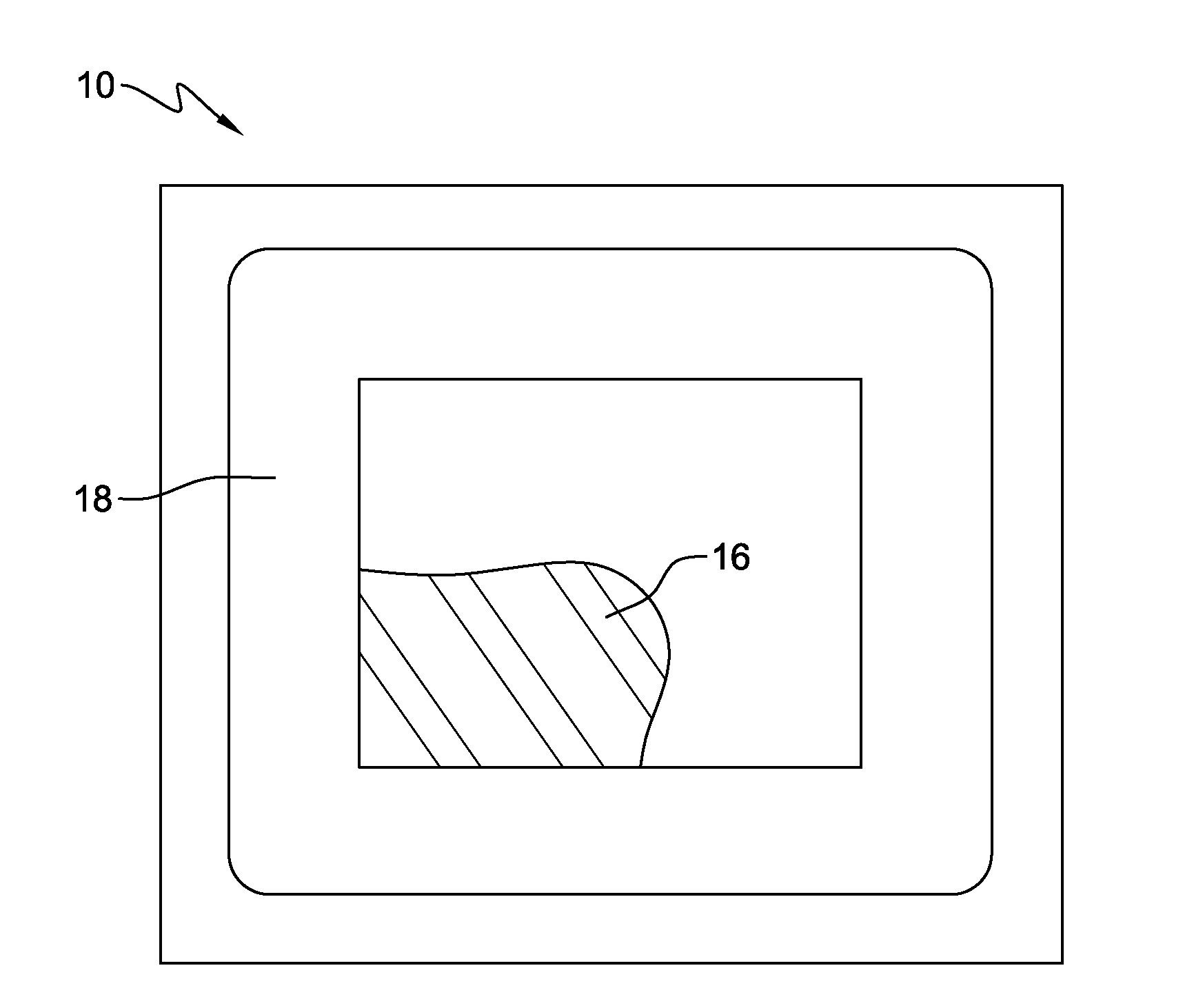
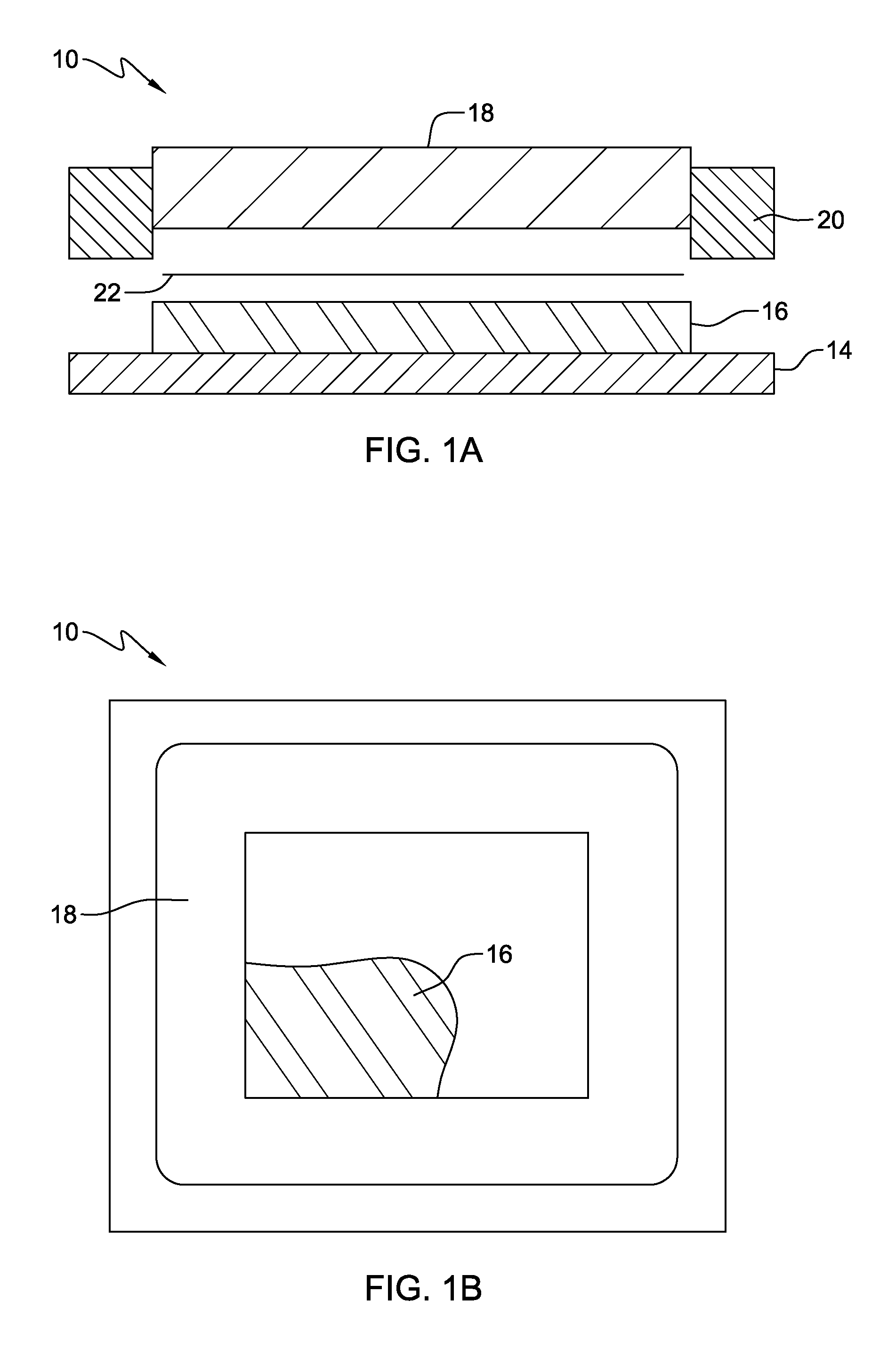
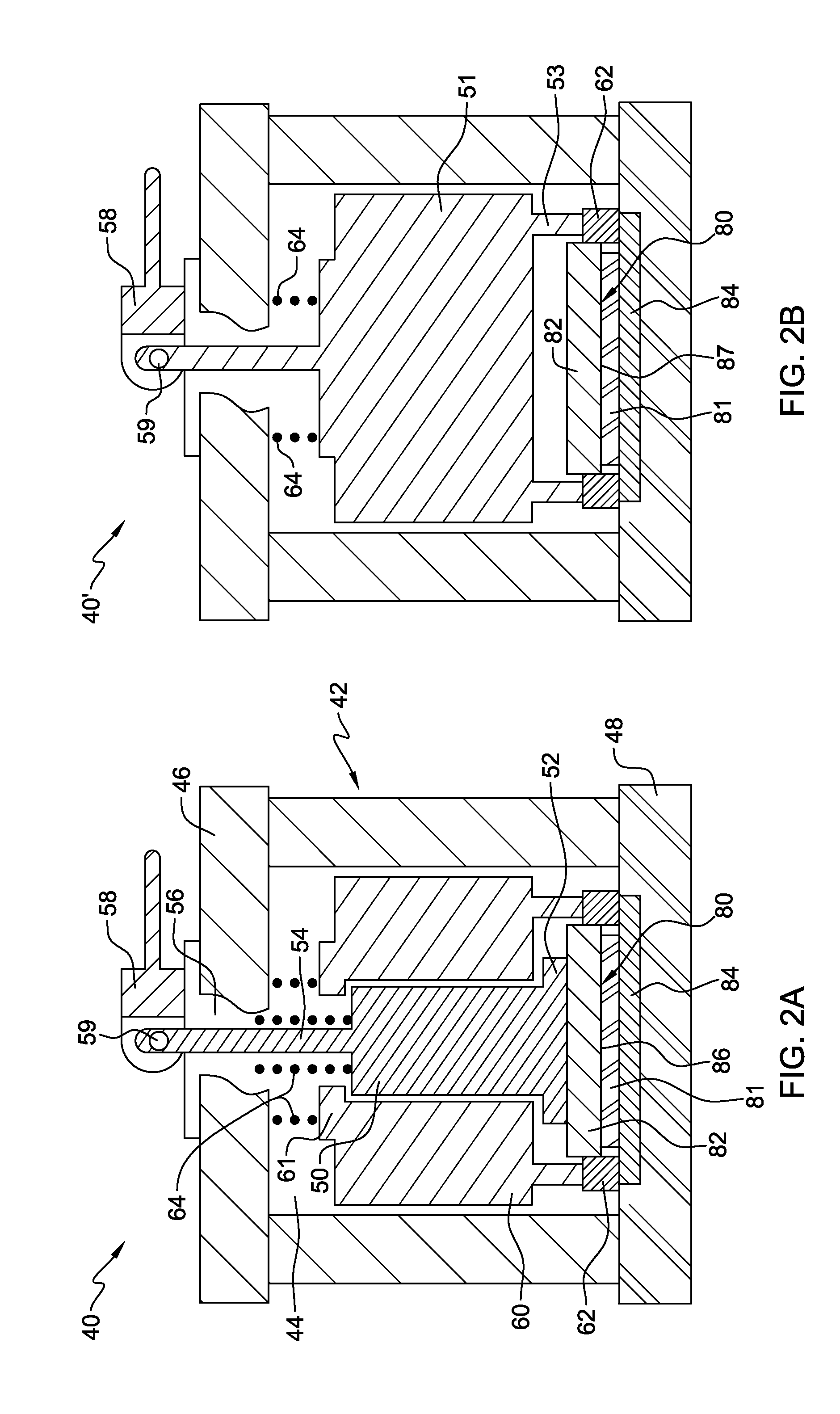
[0024]Aspects of the present invention and certain features, advantages, and details thereof, are explained more fully below with the reference to the non-limiting embodiments illustrated in the accompanying drawings. Descriptions of well-known materials, fabrication tools, processing techniques, etc., are omitted so as to not unnecessarily obscure the invention in detail. It should be understood, however, that the detailed description and the specific examples, while indicating embodiments of the invention, are given by way of illustration only, and are not by way of limitation. Various substitutions, modifications, additions and / or arrangements within the spirit and / or scope of the underlying inventive concepts will be apparent to those skilled in the art from this disclosure. Note also that reference is made below to the drawings, which are not drawn to scale for ease of understanding, wherein the same reference numbers used throughout different figures designate the same or simi...


PUM


Abstract

A coolant-cooled electronic module is provided which includes a multi-component assembly and a module lid with openings aligned over respective electronic components. Thermally conductive elements are disposed within the openings, each including opposite coolant-cooled and conduction surfaces, with the conduction surface being thermally coupled to the respective electronic component. A manifold assembly disposed over the module lid includes inner and outer manifold elements, with the inner element configured to facilitate flow of coolant onto the coolant-cooled surfaces. The outer manifold element is disposed over the inner manifold element and coupled to the module lid, with the inner and outer manifold elements defining a coolant supply manifold, and the outer manifold element and module lid defining a coolant return manifold. The coolant supply openings are in fluid communication with the coolant supply manifold, and the coolant exhaust channels are in fluid communication with the coolant return manifold.

Description

BACKGROUND[0001]Modules including, for instance, multiple integrated circuit chips mounted in an array on a substrate present unique cooling challenges. While chip size has increased over time, and power usage is more efficient than in the past, work is still needed on cooling systems and methods to remove the ever-increasing, high-density power dissipated by the integrated circuit chips. Existing art is replete with different types of thermal conduction modules (TCMs) designed to enclose and cool integrated circuit chips mounted on, for instance, a substrate. In some instances, the TCMs utilize blocks or pistons contacting the electronic components within the TCMs to remove heat. See, for instance, U.S. Pat. No. 4,500,945, and U.S. Pat. No. 6,404,638 B1, assigned to the assignee of this application.[0002]Another approach to cooling chips with TCMs has been to utilize a thermally conductive medium, such as high-thermal conductivity paste, between the top of the integrated circuit ch...

Claims


Application Information

Patent Timeline
Patent Type & Authority Applications(United States)
IPC IPC(8): H05K7/20
CPCH05K7/20281H01L23/367H01L23/3675H01L23/3677H01L23/473H01L21/4882H01L2924/0002H01L2924/00H01L23/34G06F1/20F28D15/00H05K7/20263
Inventor ARVELO, AMILCAR R.CAMPBELL, LEVI A.ELLSWORTH, JR., MICHAEL J.MCKEEVER, ERIC J.
Owner IBM CORP
Why Eureka
Try Eureka