
Storage system

a technology of automatic storage and retrieval, applied in the direction of charging stations, conveying devices, transportation and packaging, etc., can solve the problems of limiting the practical charging current that may be employed, the interface requires a very high degree of precision during connection, and is vulnerable to wear and tear

Pending Publication Date: 2022-05-12
AUTOSTORE TECH AS
View PDF0 Cites 0 Cited by
  • Summary
  • Abstract
  • Description
  • Claims
  • Application Information

AI Technical Summary

Benefits of technology

The patent describes a storage system where charging stations can be placed anywhere on a rail grid without blocking the movement of vehicles. The charging stations have a support structure that is placed within a single cell of the rail grid and at a level below the rails. This allows for flexibility in using the rail grid and ensures the charging stations can be easily moved around. The patent also describes a mechanism for preventing horizontal movement of the vehicle when the charging station is in the second position.

Problems solved by technology

Such an interface requires a very high precision during connection and is vulnerable to wear.
Further, the prior art interfaces requiring a horizontal coupling movement limit the practical charging current that may be employed.
The reason for the current limitation is that an increased current requires a correspondingly larger plug / socket which increases the friction between the two parts of the interface and consequently the force required to connect / disconnect the plug / socket.
Consequently, if the plug / socket is too large, the container-handling vehicle will not be able to connect / disconnect the plug / pin from the socket.

Method used


Image

  • Storage system
  • Storage system
  • Storage system

Examples


Embodiment Construction

[0089]In the following, embodiments of the invention will be discussed in more detail with reference to the appended drawings. It should be understood, however, that the drawings are not intended to limit the invention to the subject-matter depicted in the drawings. Furthermore, even if some of the features are described in relation to the system only, it is apparent that they are valid for the related methods as well, and vice versa.

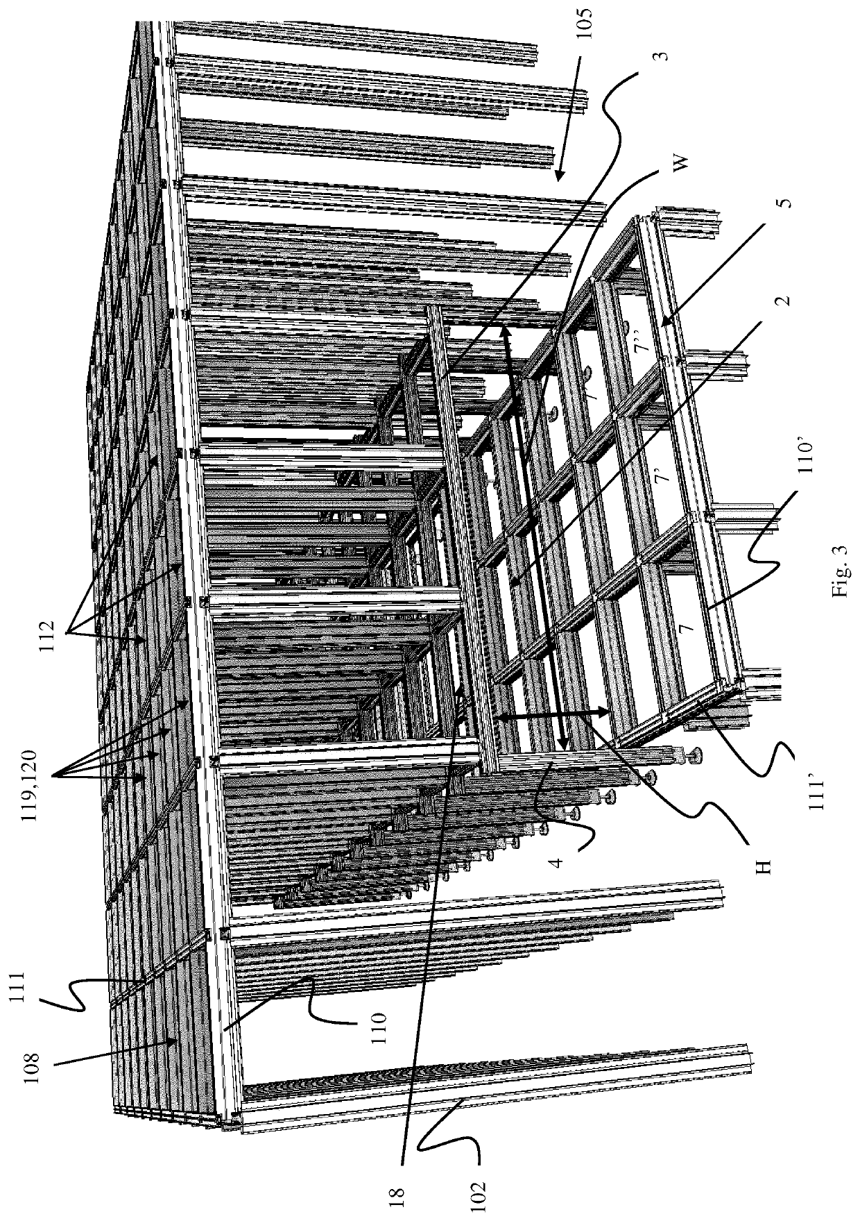
[0090]An embodiment of a storage grid for an automated storage and retrieval system according to the invention is shown in FIGS. 3 and 4 and the same storage grid featuring a container-handling vehicle 300 and a container transfer vehicle 6 is shown in FIG. 5. The number of storage columns of the grid is scaled down to better illustrate the inventive features of the storage grid. The major part of the storage grid is constructed in the same manner as in the prior art systems shown in FIGS. 1A and 2A. That is, the storage grid structure 104 comprises ver...


PUM


Abstract

A storage system includes at least one vehicle, a horizontal rail grid, and a charging system for charging a rechargeable power source of the vehicle. The vehicle includes a first set of wheels and a second set of wheels for moving the vehicle upon the rail grid. The first set of wheels is displaceable in a vertical direction between a first position, a second position, and a third position. The first set of wheels may move the vehicle in a first direction. The first and the second set of wheels are in contact with the rail grid. The second set of wheels may move the vehicle in a second direction perpendicular to the first direction. The charging system includes at least two charge-receiving elements arranged on the vehicle and connected to the power source, and a charging station including two charge-providing elements connected to a charging power source. The charging station includes an actuator operatively connected to the charge-providing elements and arranged to move the charge-providing elements in a vertical direction, such that the charge-receiving elements may be connected with the charge-providing elements when the vehicle is positioned above the charging station.

Description

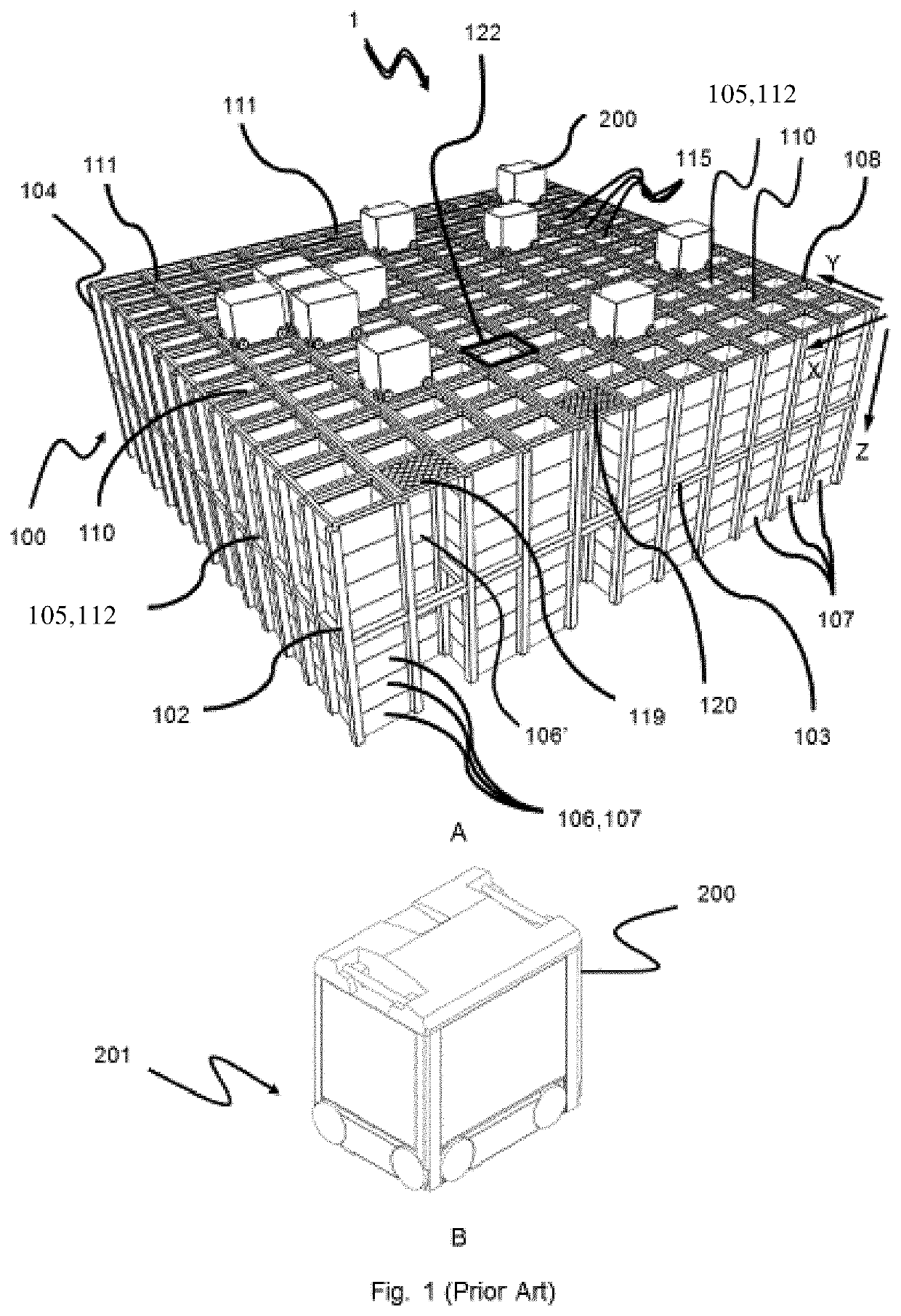
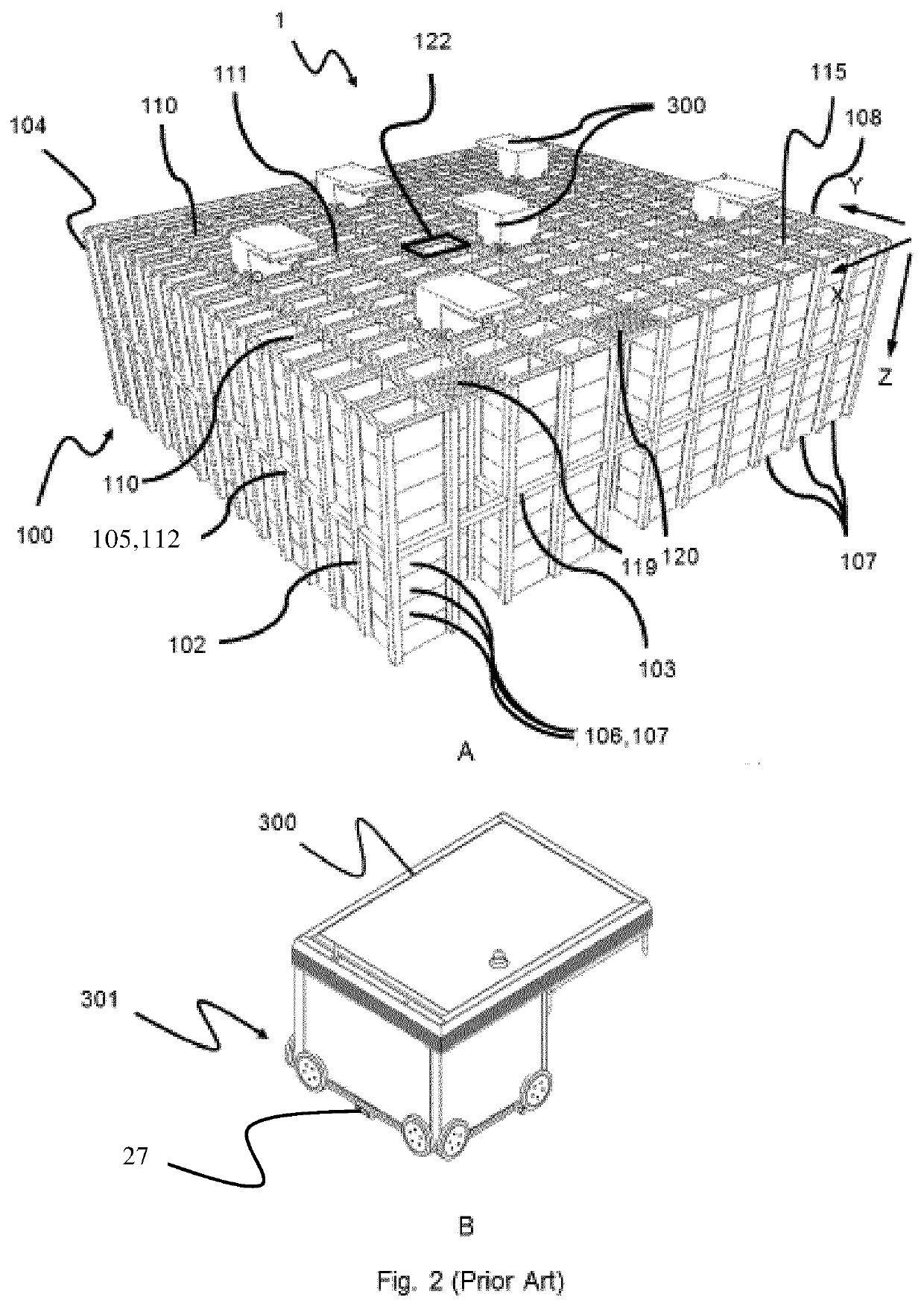
FIELD OF THE INVENTION[0001]The present invention relates to an automated storage and retrieval system comprising a charging system, and a method of using the automated storage and retrieval system.BACKGROUND[0002]FIGS. 1A and 2B disclose a typical prior art automated storage and retrieval system 1 with a framework structure 100. FIGS. 1B and 2B disclose prior art container-handling vehicles 200,300 operating in the system 1 disclosed in FIGS. 1A and 2A, respectively.[0003]The framework structure 100 defines a storage grid 104 comprising a plurality of upright members 102 and optionally a plurality of horizontal members 103 supporting the upright members 102. The members 102, 103 may typically be made of metal, e.g. extruded aluminium profiles.[0004]The storage grid 104 comprises multiple grid columns 112. A large majority of the grid columns are also termed storage columns 105, in which storage containers 106, also known as bins, are stacked one on top of another to form stacks 107...

Claims


Application Information

Patent Timeline
Patent Type & Authority Applications(United States)
IPC IPC(8): B65G1/04B60L53/36B60L53/16
CPCB65G1/0464B60L53/36B60L2200/36B60L2200/26B60L53/16Y02T10/70Y02T10/7072Y02T90/12Y02T90/14B60L2260/32B65G2201/0235B65G1/04B60L53/35B65G1/0478B65G1/0492
Inventor AUSTRHEIM, TROND
Owner AUTOSTORE TECH AS
Learn More