
Vehicle park brake actuator system

a technology of brake actuator and park brake, which is applied in the direction of mechanical control devices, instruments, process and machine control, etc., can solve the problems of large impact force within the connecting linkage, adverse effects on the durability of inability to generate undetected loud noises, so as to reduce the impact in the park brake system, reduce the impact, and reduce the effect of velocity

Inactive Publication Date: 2003-03-27
INT TRUCK INTPROP LLC
View PDF0 Cites 1 Cited by
  • Summary
  • Abstract
  • Description
  • Claims
  • Application Information

AI Technical Summary

Benefits of technology

[0003] As a result, an object of the present invention is to provide a vehicle, a park brake system for the vehicle, and connecting linkages and a park brake actuator for the vehicle that are constructed in such a manner that when the latching mechanisms of the park brake system are released, the return bumper contacts the return stop with reduced velocity and force as compared to prior art park brake systems.
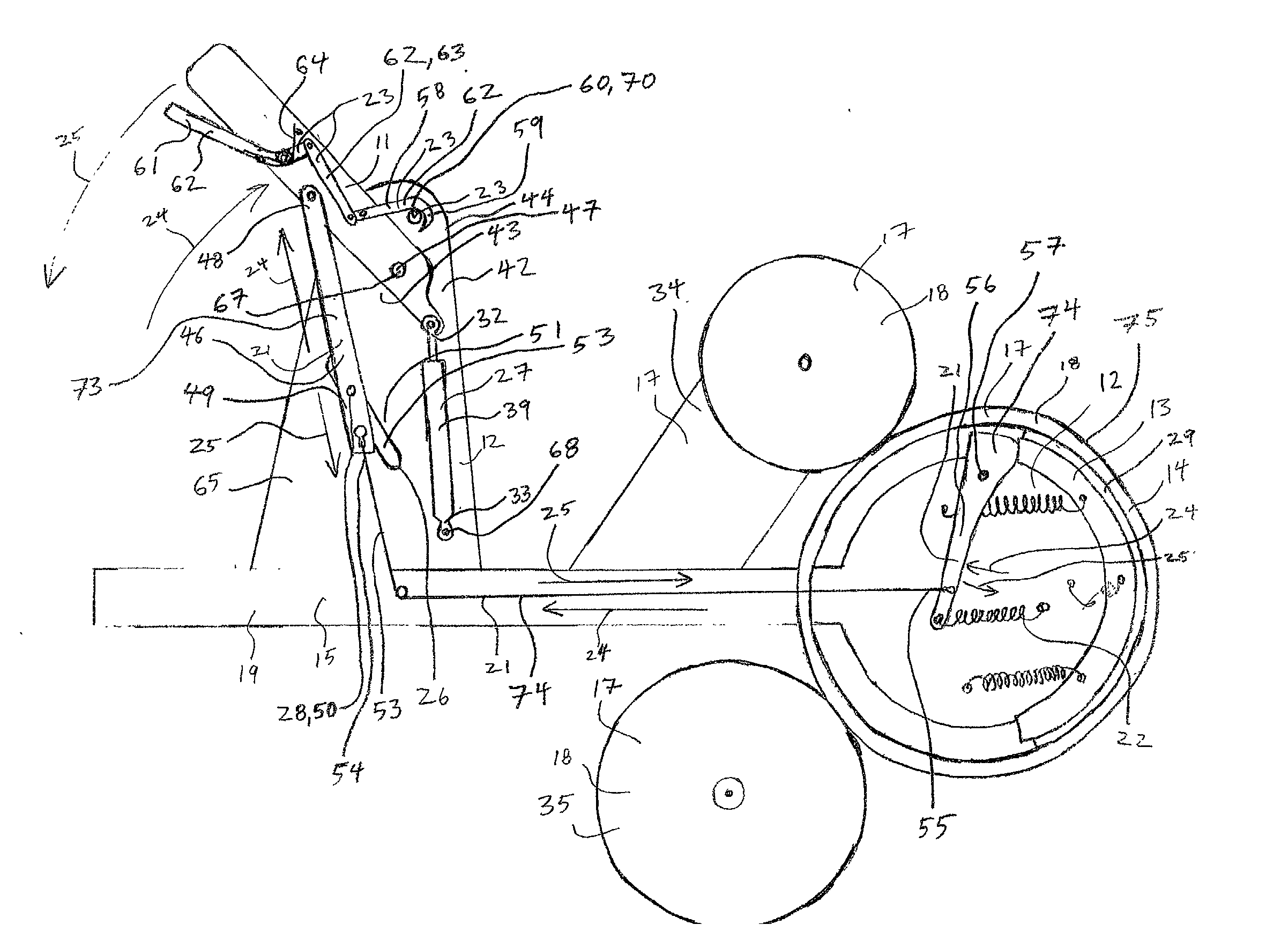
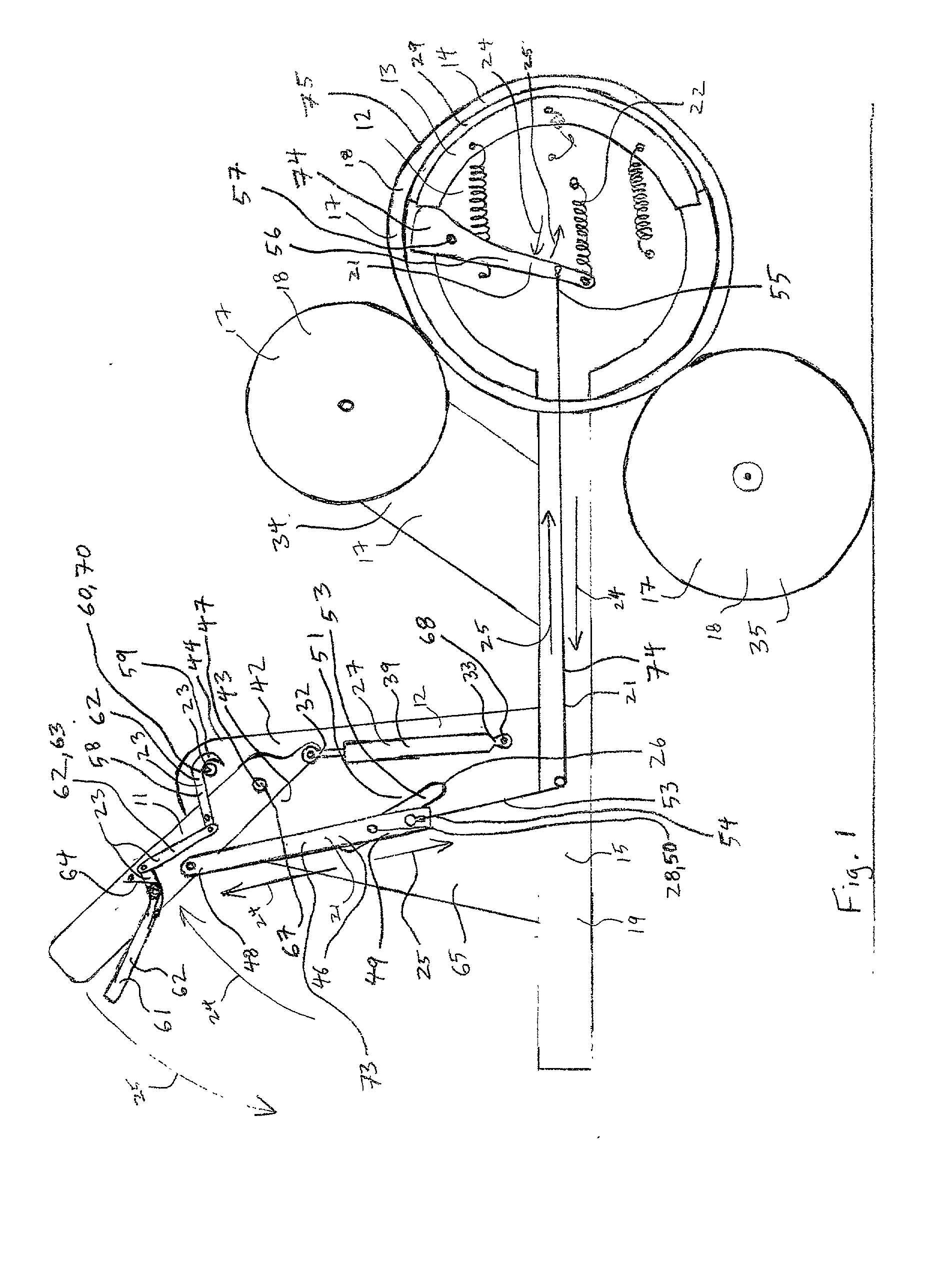
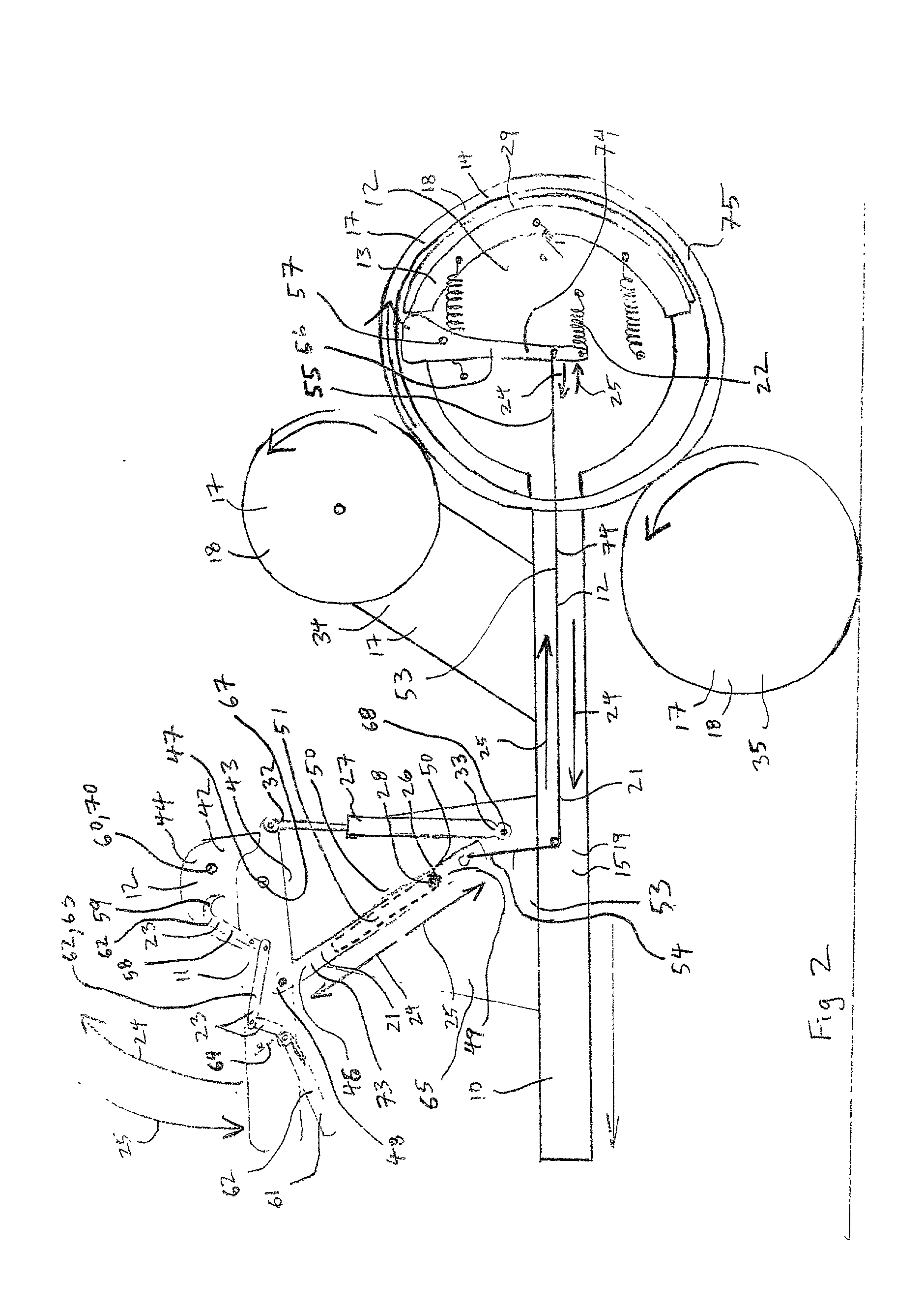
[0007] The park brake system of the present invention includes an impact reduction energy absorber for reducing the magnitude of the impact in the park brake system when the return bumper contacts the return stop. A first end of the impact reduction energy absorber is attached to either the park brake actuator or a component of the connecting linkages and a second end of the park brake actuator is connected to either the superstructure of the vehicle directly or indirectly or a component of the connecting linkages to which the first end of the impact reduction energy absorber is not attached. The impact reduction energy absorber acts to reduce the impact in the park brake system, when the return bumper contacts the return stop, in one of two ways. An impact reduction energy absorber that is connected between the superstructure of the vehicle and either the connecting linkages or the park brake actuator absorbs some of the energy transferred to the connecting linkages by the return spring while the connecting linkages and the park brake actuator are traveling in their disengaging direction toward the return stop. By absorbing some of the energy transferred to the connecting linkages while they are moving in their disengaging direction, the impact reducing energy absorber causes the connecting linkages and the park brake actuator to have diminished velocity when the return bumper contacts the return stop and, thus, the magnitude of the impact in the park brake system when the return bumper and return stop contact one another is diminished. An impact reduction energy absorber that is connected between components of the connecting linkages absorbs some of the energy transferred to the connecting linkages by the return spring in a short time period starting when the return bumper and the return stop contact one another. By absorbing energy when the return bumper and the return stop contact one another, such an impact reducing energy absorber also diminishes the magnitude of the impact in the park brake system when part of the connecting linkages or the park brake actuator contacts the return stop.

Problems solved by technology

When the connecting linkages and the park brake actuator have such high velocity when the return bumper hits the return stop, large impact forces occur within the connecting linkages and / or the park brake actuator and the return stop.
These large impact forces can have adverse effects upon the durability of the park brake system.
Undesirably loud noises can also be generated when the return bumper impacts the return stop with such considerable magnitude.
Unfortunately, in many instances users adjusted the park brake system such that the return spring applied forces to the connecting linkages of a magnitude insufficient to ensure proper operation of the park brake system.

Method used


Image

  • Vehicle park brake actuator system
  • Vehicle park brake actuator system
  • Vehicle park brake actuator system

Examples


Embodiment Construction

[0018] The present invention is a vehicle 10, and a park brake system 12 for the vehicle 10. In addition to a park brake system 12 the vehicle 10 of the present invention comprises a number of other structures, components, and systems. A vehicle 10 according to the present invention comprises a superstructure 19, which comprises a frame 15 for a vehicle 10 of body-on-frame construction or a main body structure for a vehicle of unibody construction. A vehicle 10 according to the present invention also comprises a suspension system 31 for supporting the superstructure 19 of the vehicle above the ground and for providing the vehicle 10 with a relatively low resistance to movement along the ground. A vehicle 10 according to the present invention further includes one or more body structures 30 upon or within which occupants or cargo of the vehicle 10 may ride. As was alluded to above, a vehicle 10 according to the present invention also comprises a drivetrain 17 for motivating the vehicl...


PUM


Abstract

A vehicle has a park brake system, which has set a set operational state for holding the vehicle in a parked position, and a released operational state in which the vehicle may be driven. The park brake system includes a park brake actuator and connecting linkages which are driven by an operator of the vehicle in an engaging direction in order to effect the set operational state of the park brake system. The park brake system further includes a return spring engaged to the connecting linkages in such a manner to drive them and the park brake actuator in a disengaging direction and to ensure maintenance of the released operational state of the park brake system after it is effected by an operator. The park brake system also includes an impact-reduction energy absorber such as a spring, damper, or some combination thereof for absorbing some of the energy transferred to the connecting linkages when the return spring drives the connecting linkages and the park brake actuator in their disengaging directions.

Description

[0001] This invention relates to a park brake actuator system for a vehicle. As is well known, vehicles often comprise a park brake system for preventing undesirable inadvertent motion of the vehicle when it is not in use. Park brake systems of vehicles generally comprise one or more braking components and one or more braked components complimentary to each of the one or more braked components. The braking component of each complimentary pair of a braking component and a braked component is anchored to either the superstructure of the vehicle or a drivetrain of the vehicle. The superstructure of a vehicle being the main strength providing structure of the vehicle which provides support for and ensures proper relative location of a large percentage of the other components of the vehicle. For vehicles of body-on-frame construction the superstructure of the vehicle is a frame of the vehicle and for vehicles of unibody construction the superstructure is the main body structure of the ve...

Claims


Application Information

Patent Timeline
Patent Type & Authority Applications(United States)
IPC IPC(8): B60T7/22F16D55/16F16D65/14
CPCB60T7/22F16D55/16F16D65/22Y10T74/2042F16D2125/64Y10T74/20684F16D2125/60
Inventor NOLL, MICHAEL L.HARTING, TOM E.GOODRICH, GAYLE D.DOWNES, TREVOR T.
Owner INT TRUCK INTPROP LLC
Learn More