Watertight structure for flap gate and flap gate comprising same

a technology of flap gate and watertight structure, which is applied in the direction of barrage/weir, marine site engineering, construction, etc., can solve the problem of hindering water drainag

Pending Publication Date: 2022-05-12
ASAHI INOVEX CORP
View PDF0 Cites 0 Cited by
  • Summary
  • Abstract
  • Description
  • Claims
  • Application Information

AI Technical Summary

Benefits of technology

[0023]The present invention enables, in a state in which no external force other than gravity is applied, providing a large gap between a door and a bottom face of a floodgate opening portion without providing a threshold step and ensures watertightness between the door and the floodgate opening portion when the door is closed.

Problems solved by technology

In this way, the pull-up gate needs to be operated according to the water level, causing the problem of, e.g., securing personnel necessary for the operation.
However, the bottom face of the floodgate opening portion on which a pull-up gate is installed is flat and no threshold step is provided at the bottom face.
Therefore, water drainage may be hindered even in a state in which the water level on the inner water side is low.

Method used


Image

  • Watertight structure for flap gate and flap gate comprising same
  • Watertight structure for flap gate and flap gate comprising same
  • Watertight structure for flap gate and flap gate comprising same

Examples


first embodiment

[0047]a watertight structure for a flap gate and a flap gate including the watertight structure according to the present invention will be described below with reference to the drawings.

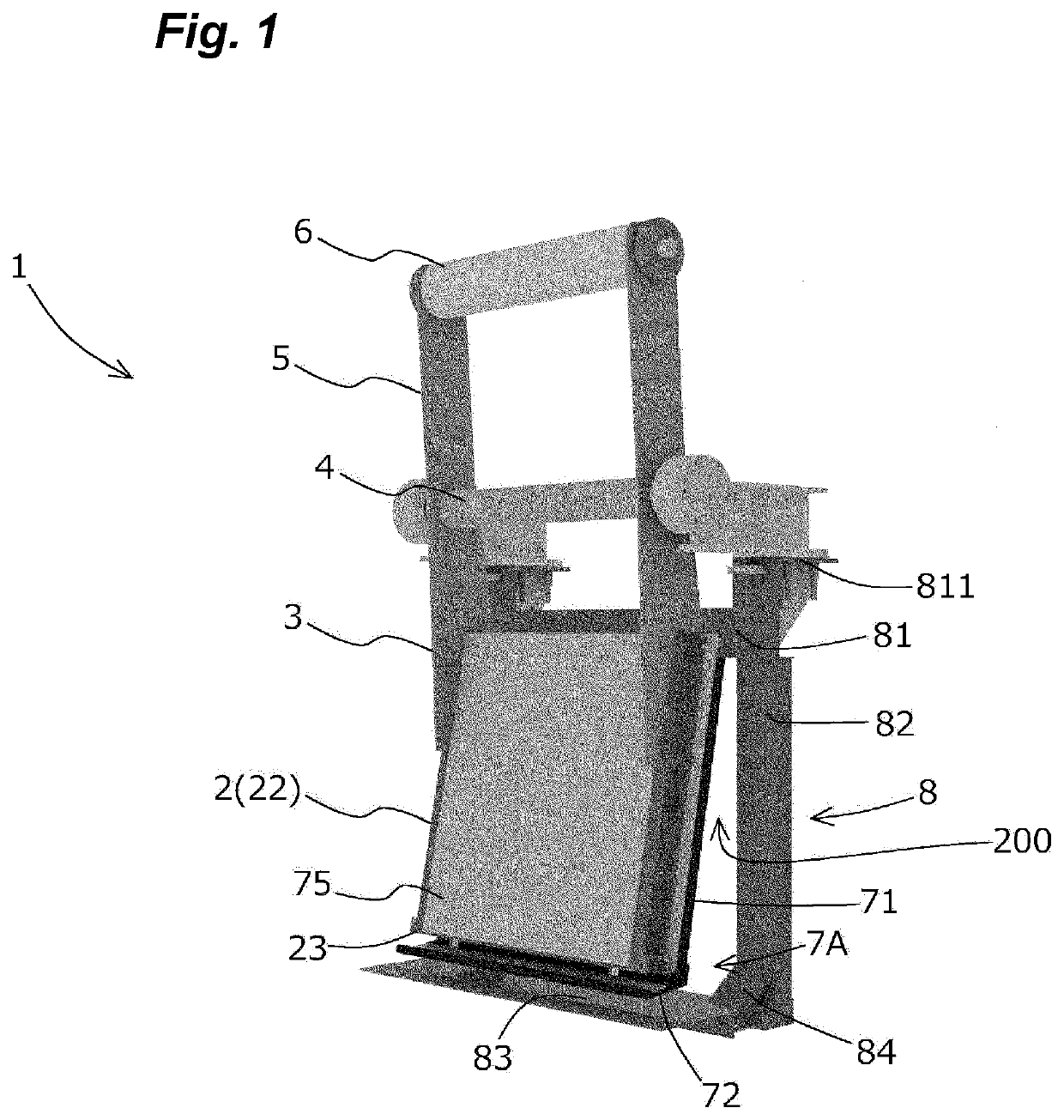
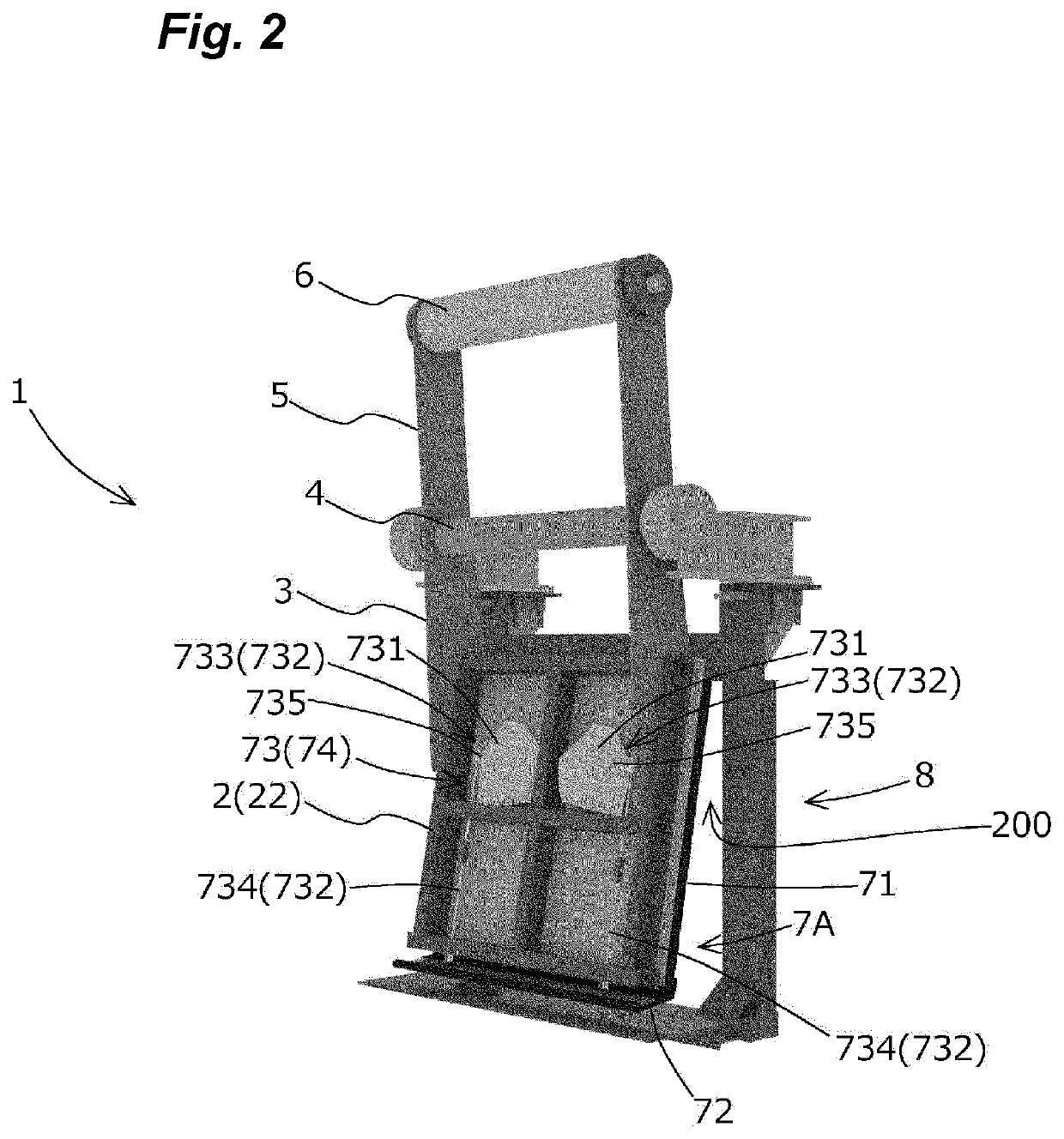
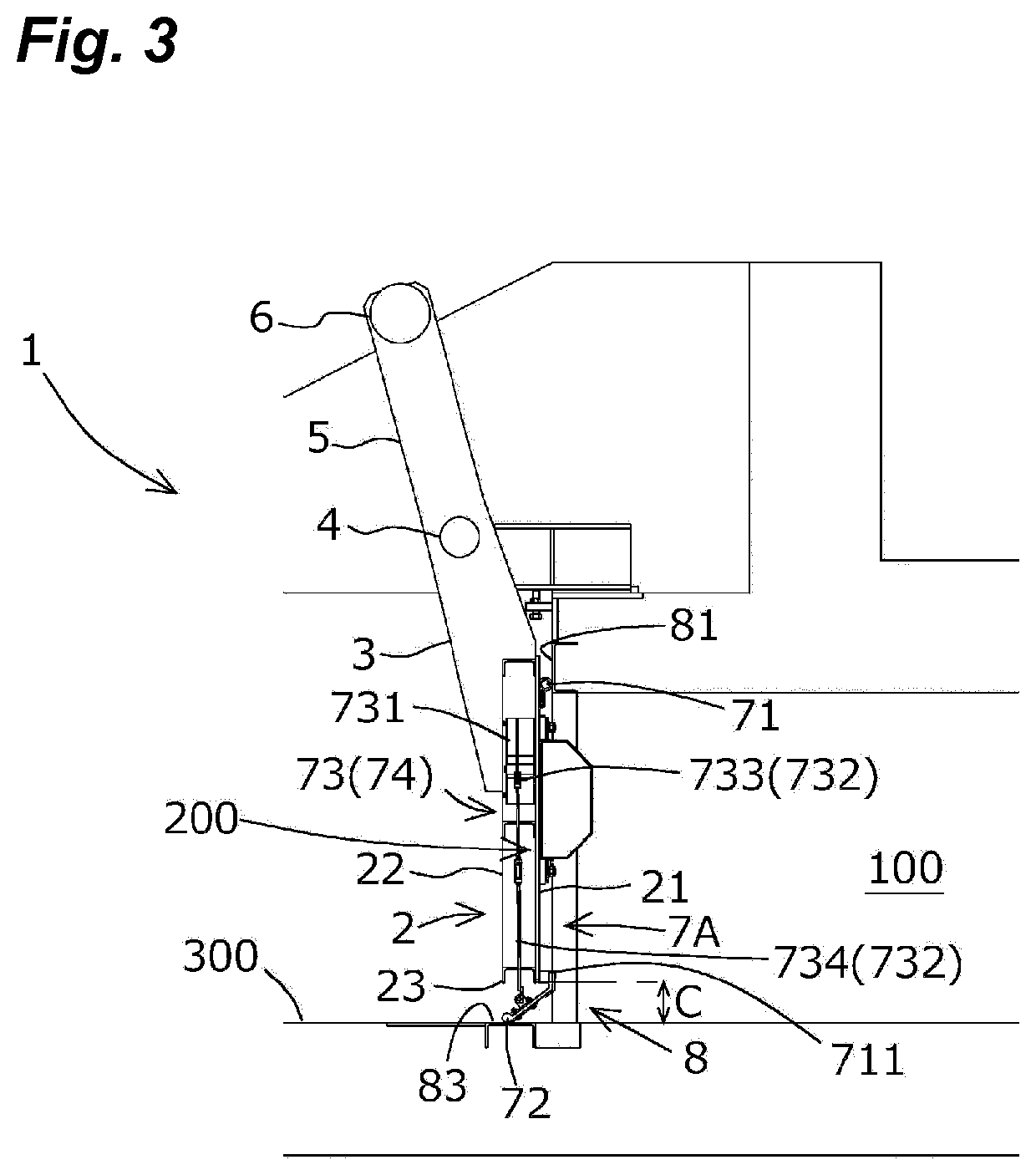
[0048]A flap gate 1 of the first embodiment is intended to automatically open and close an opening portion 200 of a floodgate 100 via a weight balance of a pivotally-supported door and water pressure, and as illustrated in FIGS. 1 to 3, includes a door 2 that opens and closes the opening portion 200, door support arms 3 that support the door 2, a swing support shaft 4 that connects the door support arms 3 and that swingably supports the door 2, weight arms 5 connected to the swing support shaft 4, a balancing weight 6 provided at upper ends of the weight arms 5, a watertight structure for a flap gate 7A ensuring watertightness between the door 2 and a doorstop 8, and the doorstop 8 disposed at the opening portion 200 of the floodgate 100. The respective components will be described in detail below.

[0...

second embodiment

[0084]As illustrated in FIG. 12, a watertight structure for a flap gate 7B of the second embodiment includes assist arms 736 provided on a gap opening-closing member 72 and open state holding weights 737 disposed at inner water-side end portions of the assist arms 736 as opening operation assist means 73, and includes a close-contact float 741 as closing operation assist means 74.

[0085]Each assist arm 736 is an arm for operating the gap opening-closing member 72 into an open state by lifting up the gap opening-closing member 72 to the outer water side as a result of the open state holding weights 737 being disposed at the inner water-side end portion, and is fixed to a lower surface of the gap opening-closing member 72 and extends to the inner water side relative to the gap opening-closing member 72. As illustrated in FIGS. 12 and 13, the assist arms 736 in the second embodiment are formed of two L-shaped angle members having an L-shape in section and are disposed at respective posi...

third embodiment

[0099]Also, the close-contact float 741 in the third embodiment is connected to inner water-side end portions of assist arms 736 by connection members 745. More specifically, each connection member 745 is formed of, e.g., a rope or a wire and includes an end to which the inner water-side end portion of the relevant assist arm 736 is connected and another end to which a lower end portion of the relevant sliding rod material 742 of the close-contact float 741 is connected. Then, in a state in which no buoyancy is generated in the close-contact float 741, each connection member 745 is connected in such a manner that no tension is applied to the inner water-side end portion of the relevant assist arm 736. On the other hand, upon a rise of the close-contact float 741 by buoyancy generated when submerged in water, tension is generated in the connection members 745, and as illustrated in FIG. 17, the connection members 745 pull up the inner water-side end portions of the respective assist ...


PUM


Abstract

A watertight structure in a flap gate 1 provided with a weight-balance supported door 2 to open an opening 200 of a floodgate 100 in a state in which no external force other than gravity is applied, wherein the structure has: a gap opening-closing member 72 that oscillates in the water flow direction and opens and closes a gap C, wherein the gap C is provided between the lower edge 23 of the door 2 and the bottom face 300 of the floodgate 100 in a state in which the door 2 is blocking the floodgate 100; and an opening operation assist means 73 for operating the gap opening-closing member 72 so as to be in an open state by lifting same toward the outer water side.

Description

TECHNICAL FIELD[0001]The present invention relates to a watertight structure for a flap gate, the watertight structure being capable of opening and closing a gap between a lower edge of a door that opens and closes an opening portion of a floodgate and a bottom face of the floodgate, and a flap gate including the watertight structure.BACKGROUND ART[0002]Conventionally, gates for preventing backflow caused by a flood, a storm surge or the like are provided in sluice gates and floodgates installed in rivers, lakes, seacoasts or the like. As an example of the gates that open and close an opening portion of a floodgate, there is a pull-up gate that opens the floodgate opening portion by pulling a door upward. In general, a rack lift is used for lifting the door up and down. In normal times, the floodgate opening portion is kept open to allow water flowing from the inner water side to be drained to the outer water side. If a backflow to the inner water side occurs due to a rise in water ...

Claims


Application Information

Patent Timeline
Patent Type & Authority Applications(United States)
IPC IPC(8): E02B7/44
CPCE02B7/44E02B7/54
Inventor ONODERA, TETSUOSASAYAMA, KOJITSUCHIYA, TOSHIO
Owner ASAHI INOVEX CORP
Why Eureka
Try Eureka