Electrical wire-connecting structure and method for manufacturing electrical wire-connecting structure

a technology of electrical wires and wire connections, applied in the field of components, can solve the problems of easy corrosion of metals, and achieve the effect of ensuring watertightness

Active Publication Date: 2017-10-17
FURUKAWA ELECTRIC CO LTD +1
View PDF18 Cites 1 Cited by
  • Summary
  • Abstract
  • Description
  • Claims
  • Application Information

AI Technical Summary

Benefits of technology

[0017]According to the present invention, the terminal having the tubular portion is prepared in which the conductor insertion portion into which the conductor portion is inserted is formed with a smaller diameter than the covering insertion portion into which the covering portion of the insulated electrical wire is inserted, and an inner diameter of the covering insertion portion is in the range of 1.0 to 1.7 times an outer diameter of the covering portion; the insulated electrical wire is inserted into the tubular portion; and the covering insertion portion and the covering portion are compressively crimped. Accordingly, it is easy to insert the conductor portion of the insulated electrical wire into the conductor insertion portion, and easy to ensure watertightness between the terminal and the insulated electrical wire.

Problems solved by technology

As such, the metals will easily corrode if water enters.
Patent Documents 1 and 2, which disclose structures in which an intermediate cap or a waterproof tube is provided between an open-barrel crimping terminal and an aluminum electrical wire, can be given as examples of techniques for improving watertightness, but these techniques have difficult aspects such as a complicated manufacturing process.

Method used


Image

  • Electrical wire-connecting structure and method for manufacturing electrical wire-connecting structure
  • Electrical wire-connecting structure and method for manufacturing electrical wire-connecting structure
  • Electrical wire-connecting structure and method for manufacturing electrical wire-connecting structure

Examples


Embodiment Construction

[0022]Next, an embodiment of the present invention will be described with reference to the drawings.

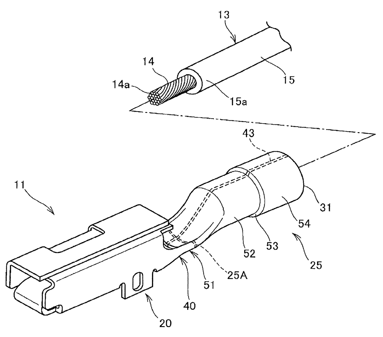
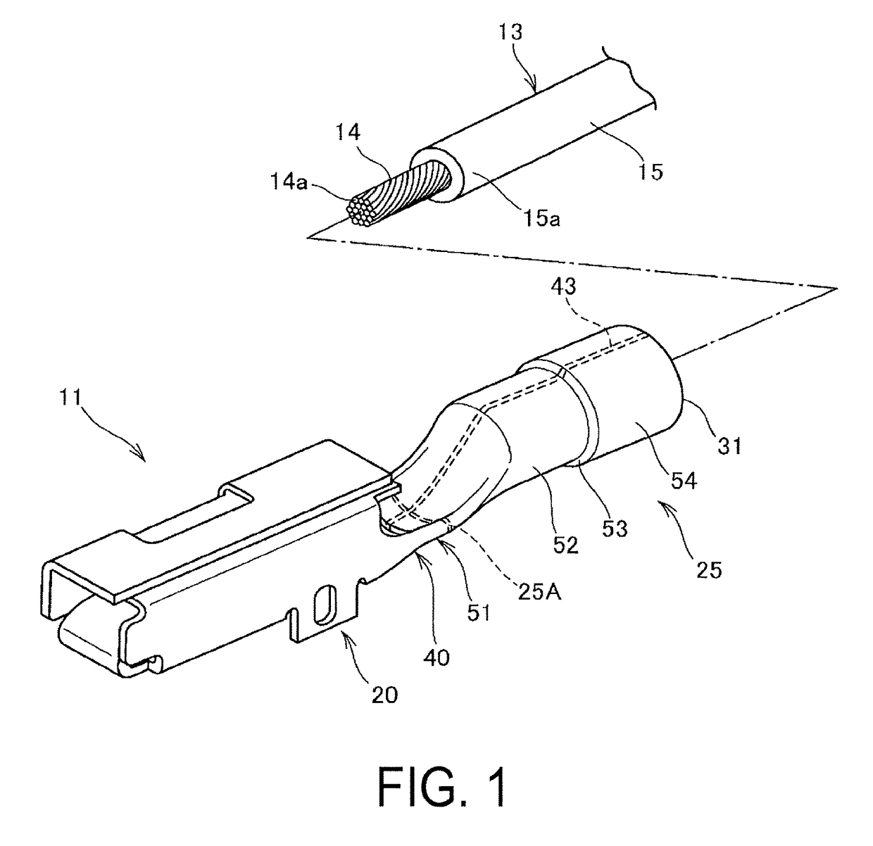
[0023]FIG. 1 is a perspective view illustrating an electrical wire-connecting structure according to the embodiment before being joined through crimping.

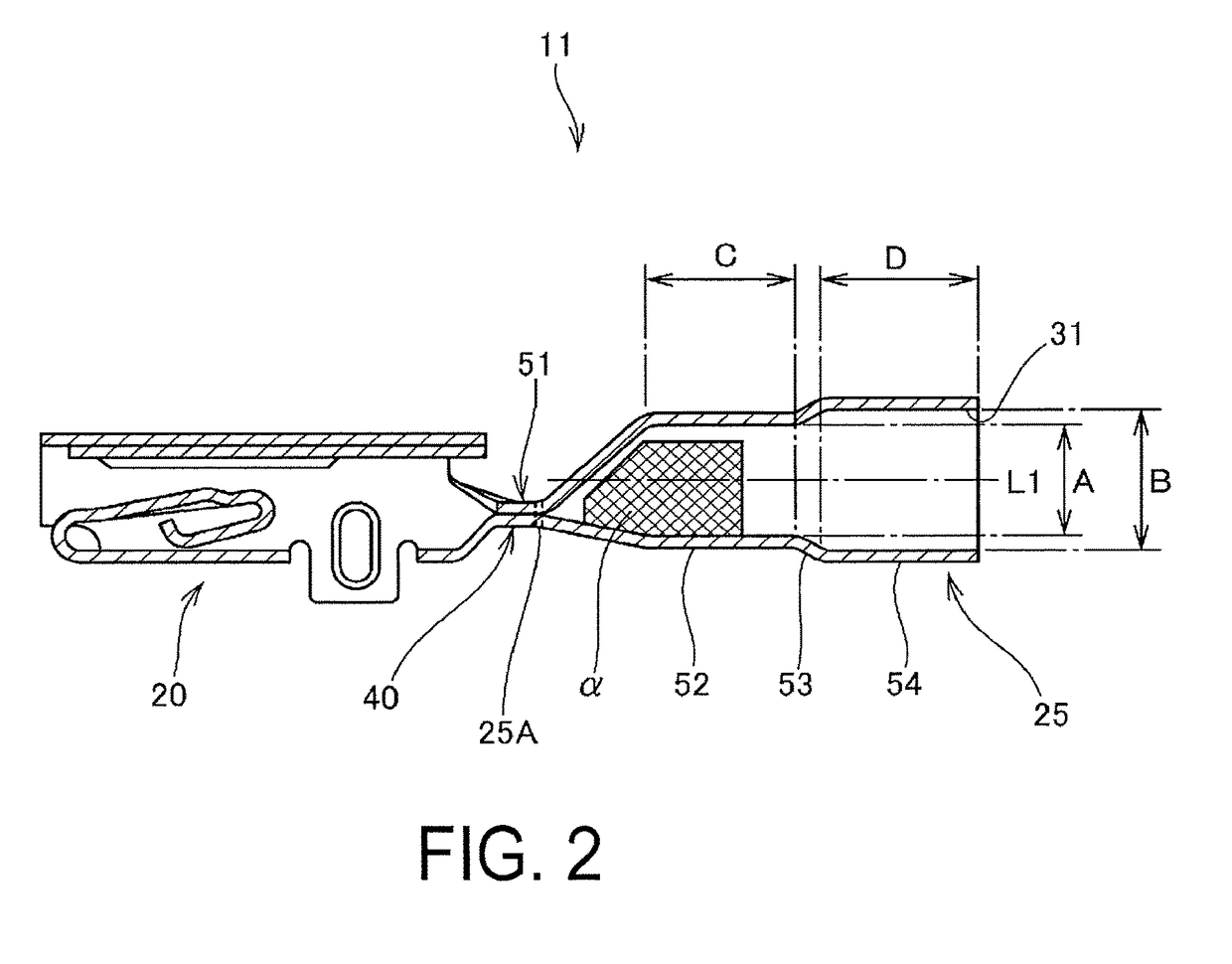
[0024]This electrical wire-connecting structure 10 is used in a wire harness in an automobile, for example. The electrical wire-connecting structure 10 includes a crimping terminal (tube terminal) 11 and an electrical wire (an insulated electrical wire) 13 joined through crimping (also called bonded through crimping) to the crimping terminal 11. The crimping terminal 11 includes a female terminal box portion 20 and a tubular portion 25, as well as a transition portion 40 that spans therebetween.

[0025]The crimping terminal 11 is primarily manufactured from a metal base material (copper or a copper alloy, in the present embodiment) to ensure electrical conductivity and mechanical strength. For example, brass, a Corson-based copper alloy...


PUM


Abstract

Provided is an electrical wire-connecting structure, and a manufacturing method thereof, with which it is easy to ensure watertightness between a crimping terminal and an insulated electrical wire. A crimping terminal (11) having a tubular portion (25) is prepared in which a first cylindrical portion (52) into which a core wire portion (14) of an electrical wire (13) is inserted is formed with a smaller diameter than a second cylindrical portion (54) into which an insulation covering portion (15) of the electrical wire (13) is inserted, and an inner diameter of the second cylindrical portion (54) is in the range of 1.0 to 1.7 times an outer diameter of the insulation covering portion (15). The electrical wire (13) is inserted into the tubular portion (25), and the second cylindrical portion (54) and the insulation covering portion (15) are compressively crimped.

Description

TECHNICAL FIELD[0001]The present invention relates to components that handle the conduction of electricity. More particularly, the present invention relates to an electrical wire-connecting structure composed of an electrical wire and a terminal and a method for manufacturing an electrical wire-connecting structure.BACKGROUND ART[0002]In, for example, automobiles, wire harnesses (groups of electrical wires) in which a plurality of electrical wires are bundled together are laid and a plurality of electrical devices are electrically connected to each other by the wire harnesses. Wire harnesses are connected to electrical devices, or wire harnesses are connected to each other, via connectors provided to both the wire harnesses and devices. For such an electrical wire, an insulated electrical wire formed by covering a core wire portion (a conductor portion) with an insulator is used. For example, a crimping terminal is connected to an end portion of the core wire exposed by peeling away...

Claims


Application Information

Patent Timeline
Patent Type & Authority Patents(United States)
IPC IPC(8): H01R4/10H01R4/18H01R43/048H01R4/62H01R13/52
CPCH01R4/183H01R4/62H01R43/048H01R13/52
Inventor KAWAMURA, YUKIHIROTONOIKE, TAKASHI
Owner FURUKAWA ELECTRIC CO LTD
Why Eureka
Try Eureka