Robotic surgical methods and apparatuses

a robotic and surgical technology, applied in the field of robotic surgical methods and apparatuses, can solve problems such as instrument collisions

Pending Publication Date: 2022-05-26
DULUTH MEDICAL TECH INC
View PDF0 Cites 3 Cited by
  • Summary
  • Abstract
  • Description
  • Claims
  • Application Information

AI Technical Summary

Problems solved by technology

Some robotic systems are not traditional robots, in that once activated, they do not automatically move the attached instrument along a pre-programmed path of travel.
However, there may be a situation in which, after the procedure begins, it becomes apparent that the instrument may collide with an object at the surgical site against which such contact is undesirable.

Method used


Image

  • Robotic surgical methods and apparatuses
  • Robotic surgical methods and apparatuses
  • Robotic surgical methods and apparatuses

Examples


example 1

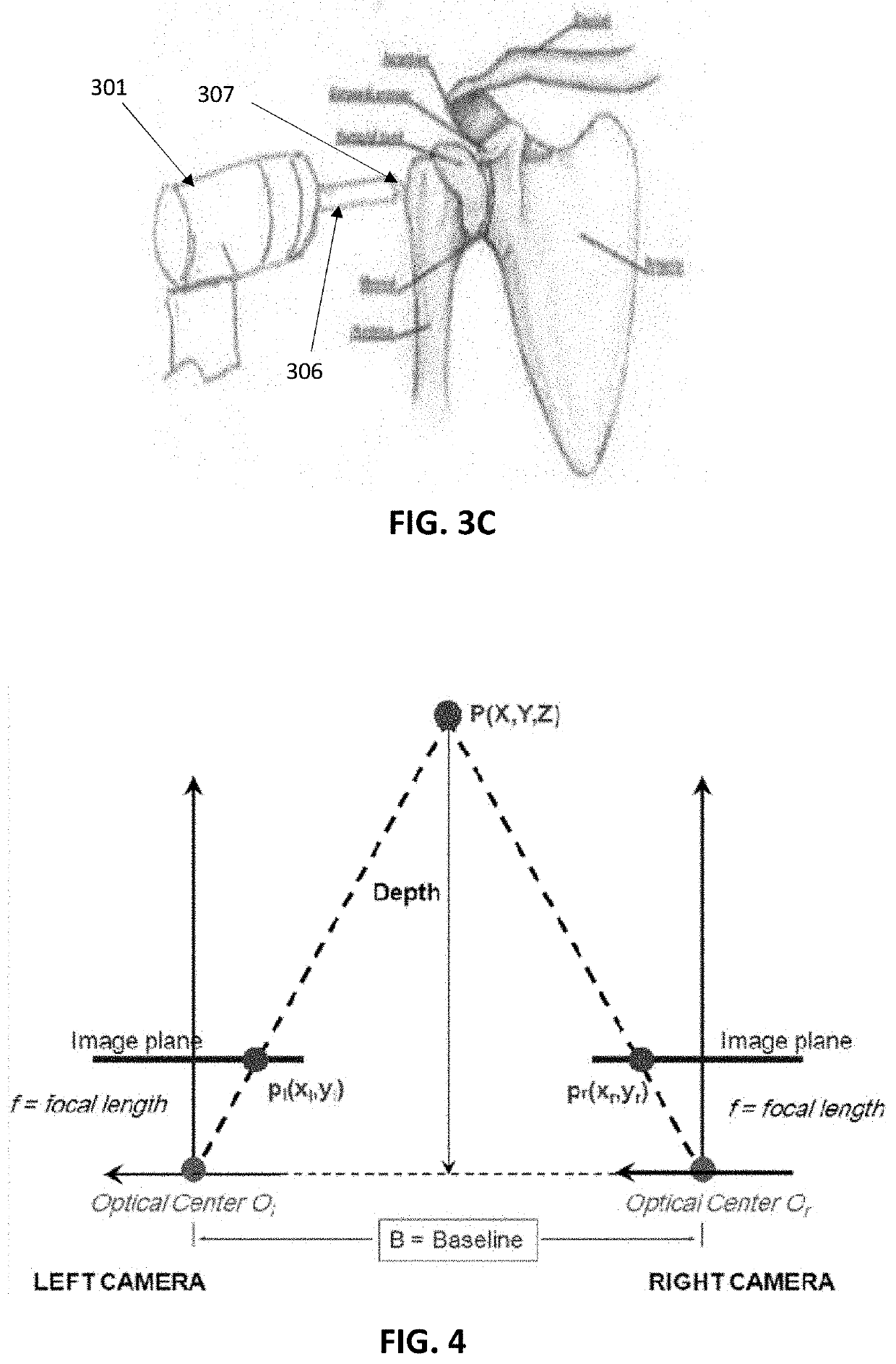
[0096]FIG. 8 illustrates one example of the methods described above, in which an image is taken by a camera (an arthroscopic view of a shoulder). The system may accurately detect the attached portion of the subscapularis to the humeral head, as shown in the bounding box 801 marked in FIG. 8. This identified region from each of the images may then be used to determine the location of the tool 803 and / or robotic arm. As the robotic arm and / or tool move, the images may be constantly updated. In some variations, multiple images may be taken and identified from different positions to triangulate the depth and thus the x, y, z position of the tool and / or robotic arm. In this example, the system recognizes both the subscapularis and the humeral head.

[0097]In general, any appropriate end effector devices (“end effector”) may be used. For example, an end effector device may be a custom end effector device. The dimensions of the end effectors may be known (e.g., preprogrammed, predetermined, ...


PUM


Abstract

Robotic surgical methods and apparatuses, including systems, for determining positioning information using a combination of AI landmark-identification and visual imaging. Also described herein are methods and apparatuses for determining how to train the AI. Also described herein are end effector devices that may be used with any of the robotic surgical methods and apparatuses. Also described herein designs and techniques incorporating AR into robotic surgical procedures.

Description

CROSS REFERENCE TO RELATED APPLICATIONS[0001]This application is a Continuation of and claims priority to PCT / US2020 / 046077 filed 13 Aug. 2020 which in turn claims priority from U.S. Provisional 62 / 886,302 filed 13 Aug. 2019, the entirety of which are both hereby incorporated by referenceINCORPORATION BY REFERENCE[0002]All publications and patent applications mentioned in this specification are herein incorporated by reference in their entirety to the same extent as if each individual publication or patent application was specifically and individually indicated to be incorporated by reference.FIELD[0003]The apparatuses and methods described herein relate generally to tools and system for facilitating orthopedic procedures.BACKGROUND[0004]Robotic devices may be useful to assist in the performance of surgical procedures. A robotic device typically includes a moveable arm that comprises one or more linkages. The arm has a free distal end that can be placed and moved with a very high de...

Claims


Application Information

Patent Timeline
Patent Type & Authority Applications(United States)
IPC IPC(8): A61B34/30B25J9/16G06T7/00G06T7/70G06T7/50G06N3/04
CPCA61B34/30B25J9/1697G06N3/0454G06T7/70G06T7/50G06T7/0012A61B34/20A61B34/10G06N3/08A61B2034/2065A61B2034/105A61B2090/365A61B2090/371A61B90/361G16H20/40G16H50/50G16H30/40A61B34/32A61B34/76A61B17/16A61B2017/00084G06N3/045
Inventor SPYKERMAN, RACHEL R.FOURKAS, MICHAEL G.SOLOMON, DANIEL J.BARRY, JEFFREY J.DANA, RUCHISEDDIQUI, FRED R.
Owner DULUTH MEDICAL TECH INC
Why Eureka
Try Eureka