Supercharge Your Innovation With Domain-Expert AI Agents!

Gas turbine engine with improved vigv shielding

a technology of vigv shielding and gas turbine engine, which is applied in the direction of machines/engines, stators, liquid fuel engines, etc., can solve the problems of ice buildup on ess vanes and igvs, increased risk, and added weigh

Active Publication Date: 2022-05-26
ROLLS ROYCE PLC
View PDF2 Cites 0 Cited by
  • Summary
  • Abstract
  • Description
  • Claims
  • Application Information

AI Technical Summary

Benefits of technology

The patent text describes a method to protect vehicles from ice buildup during cold weather conditions. The method involves positioning the vehicles in a way that they are located within low concentration regions of supercooled liquid water droplets. This helps to prevent ice buildup on the vehicles and ensures safe driving.

Problems solved by technology

In such circumstances ice may build up on ESS vanes and IGVs.
In particular, there is a risk of icing when the design of the engine is such that the fan imparts only a low temperature rise to the air, and to a lesser extent the risk is exacerbated by lower fan blade rotational speed, such as in large and medium geared gas turbine engines, and a reduced number of fan blades.
Ice attached to the surface of a vane may effectively change the geometry of the vane, such that oncoming flow is presented with a surface that is not to design specification, and add unnecessary weight.
This may ultimately result in lower engine efficiency and / or performance.
Furthermore, ice formed on the vanes can break away therefrom in a process known as “shedding”, which can cause ice impacts that may damage downstream components of the engine, in particular rotating components of the engine.
For example ice shed from the ESS vanes and / or (V)IGVs may strike and damage rotating downstream compressor blade rows.
A disadvantage of known anti-icing and de-icing systems is that they require additional hardware, in the form of bleeds and ducting for hot air, or heating elements and their associated control systems, which add weight and complexity to the engine.
In addition, the need for warmed and pressurised air, or for electrical power, is detrimental to the overall efficiency and performance of the engine.

Method used


Image

  • Gas turbine engine with improved vigv shielding
  • Gas turbine engine with improved vigv shielding
  • Gas turbine engine with improved vigv shielding

Examples


Embodiment Construction

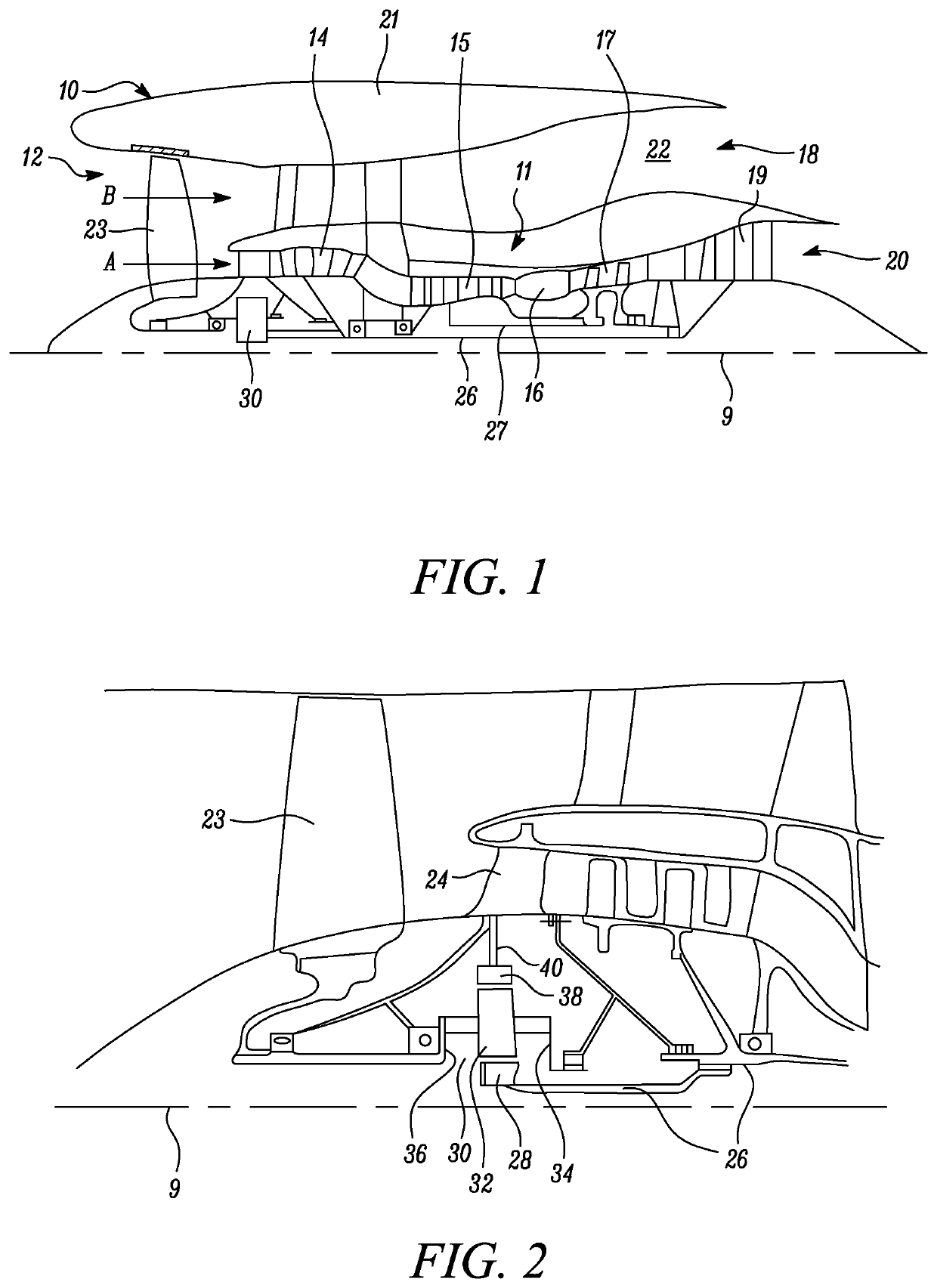
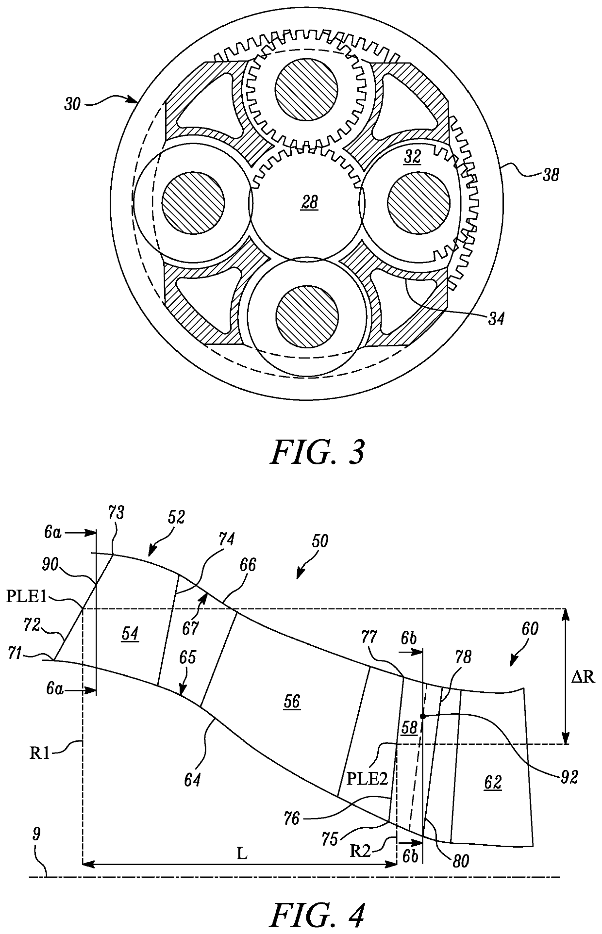
[0076]FIG. 1 illustrates a gas turbine engine 10 having a principal rotational axis, or engine main axis 9. The engine 10 comprises an air intake 12 and a propulsive fan 23 that generates two airflows: a core airflow A and a bypass airflow B. The gas turbine engine 10 comprises a core 11 that receives the core airflow A. The engine core 11 comprises, in axial flow series, a low pressure compressor 14, a high-pressure compressor 15, combustion equipment 16, a high-pressure turbine 17, a low pressure turbine 19 and a core exhaust nozzle 20. A nacelle 21 surrounds the gas turbine engine 10 and defines a bypass duct 22 and a bypass exhaust nozzle 18. The bypass airflow B flows through the bypass duct 22. The fan 23 is attached to and driven by the low pressure turbine 19 via a shaft 26 and an epicyclic gearbox 30. In some arrangements, the gas turbine engine 10 may not comprise a gearbox 30.

[0077]In use, the core airflow A is accelerated and compressed by the low pressure compressor 14 ...


PUM


Abstract

A gas turbine engine includes: a fan rotating about an engine main axis; a core duct; an engine core; an Engine Section Stator (ESS) including a plurality of ESS vanes and arranged in the core duct downstream of the fan; and a plurality of variable inlet guide vanes (VIGV) adapted to rotate about a pivot axis and arranged in the core duct downstream of the ESS. The VIGV vanes are arranged angularly rotated with respect to the ESS vanes such that the VIGVs are shielded by the ESS, thereby protecting the VIGVs from icing and from ice shedding from the ESS vanes.

Description

CROSS-REFERENCE TO RELATED APPLICATIONS[0001]This specification is based upon and claims the benefit of priority from UK Patent Application Number 2018264.8 filed on Nov. 20, 2020, the entire contents of which are incorporated herein by referenceBACKGROUND1. Field of the Disclosure[0002]The present disclosure relates to a gas turbine engine and more particularly to a gas turbine engine including components, such as vanes, which may be subject to icing.2. Description of the Related Art[0003]Gas turbine engines are typically employed to power aircraft. A gas turbine engine generally comprises, in axial flow series from front to aft, a fan, a core and an exhaust nozzle. The core comprises one or more compressors, a combustor, and one or more turbines. An air intake is provided for the engine. Air entering the air intake is accelerated by the fan to produce two air flows: a first air flow (core engine flow) through a core duct into the compressor and a second air flow (bypass flow) to p...

Claims


Application Information

Patent Timeline
Patent Type & Authority Applications(United States)
IPC IPC(8): F01D9/04
CPCF01D9/041F05D2240/12F05D2220/32F01D9/02F02K3/06F01D17/162F05D2240/121F05D2240/122F01D25/02F01D9/04F01D5/143F04D29/563F02C7/042Y02T50/60F05D2220/323
Inventor JONES, GEOFFREY BSPALTON, EDWARD JMACDOUGALL, DUNCAN A
Owner ROLLS ROYCE PLC
Features
  • R&D
  • Intellectual Property
  • Life Sciences
  • Materials
  • Tech Scout
  • Unparalleled Data Quality
  • Higher Quality Content
  • 60% Fewer Hallucinations
Learn More