
Control of the positioning and continuity of threads in a loom

a technology of positioning continuity and loom, which is applied in the field of looms, can solve the problems of high number of carbon threads to be placed, high labor intensity of warp preparation, and high cost of operation

Pending Publication Date: 2022-06-02
SN DETUDE & DE CONSTR DE MOTEURS DAVIATION S N E C M A
View PDF23 Cites 0 Cited by
  • Summary
  • Abstract
  • Description
  • Claims
  • Application Information

AI Technical Summary

Benefits of technology

This patent describes a weaving installation that reduces wear and tear on carbon threads during the weaving process. The installation includes multiple pairs of electrical contacts that make contact with the threads, and each contact has a rotatable, electrically conductive element to prevent wear and tear on the threads. The installation also includes an open-circuit detection circuit to prevent arcing. Additionally, the process allows for real-time detection and correction of broken threads, ensuring a compliant weave.

Problems solved by technology

The preparation of the warp, also called warping, is a very tedious operation because it consists in placing each carbon thread one after the other in perforated boards to order the threads for weaving or in heddle eyes and to fix them with a thread calling system present at the exit of the loom.
This operation is a source of errors because the number of carbon threads to be placed can be very high, for example more than a hundred, with a very small distance between each thread.
In addition, even with proper warp preparation, it is possible for one or more threads to break during weaving.
The breakage of a carbon thread among all the warp threads is sometimes difficult to spot.
In any case, the incorrect placement of thread at the beginning or the breaking of a thread during weaving has major consequences because the fibrous reinforcement obtained does not have all the required mechanical characteristics, which leads to a risk of rejects and thus of waste of raw material.

Method used


Image

  • Control of the positioning and continuity of threads in a loom

Examples


Embodiment Construction

[0019]The invention applies generally to looms used to produce fibrous textures with carbon fiber threads, the threads being stored upstream of a loom in bobbins and unwound to the loom exit. The invention applies in particular to Jacquard-type looms used in particular to produce fibrous textures or fabrics by two-dimensional (2D) and three-dimensional (3D) or multilayer weaving between layers of warp threads and layers of weft threads.

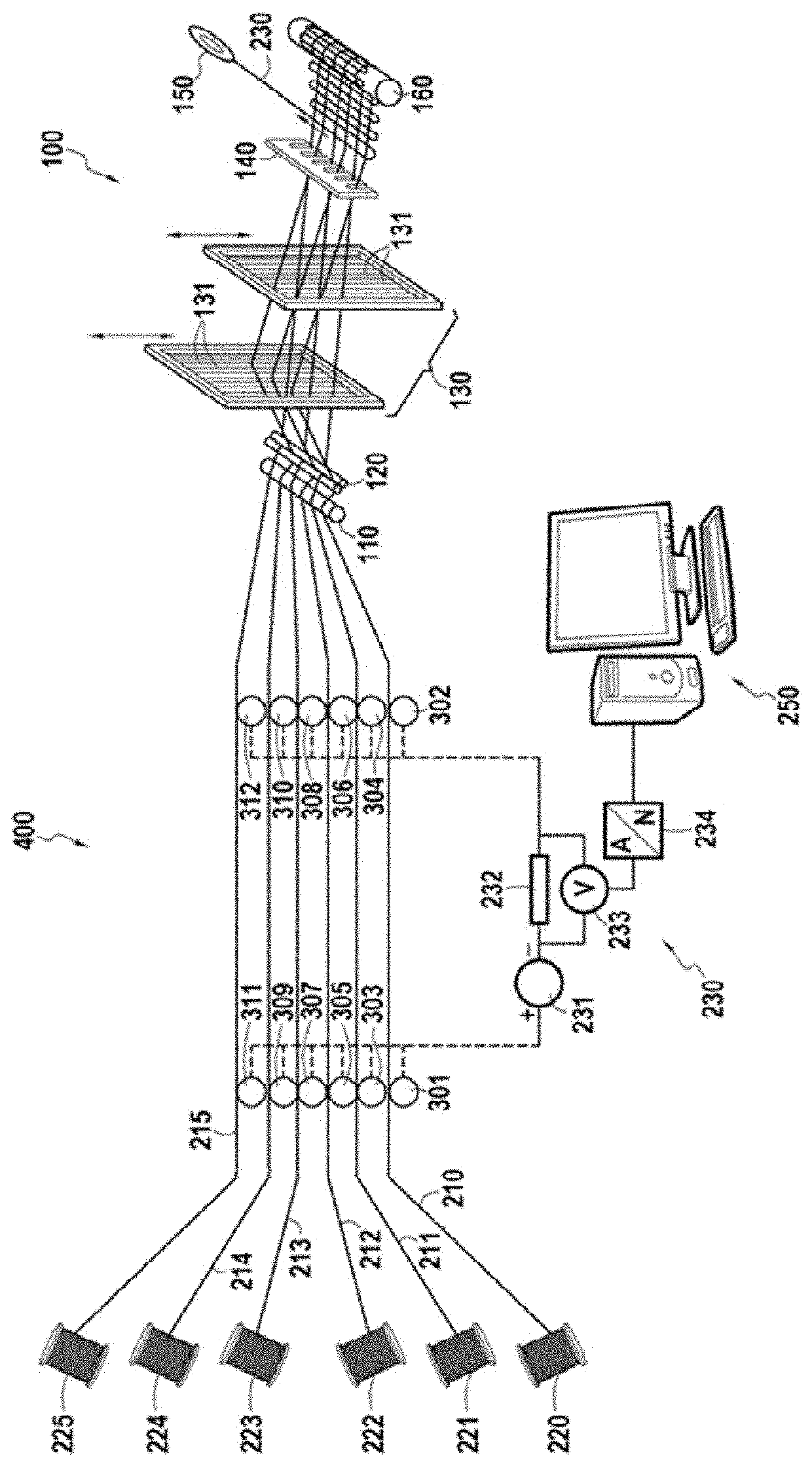
[0020]FIG. 1 shows very schematically a weaving installation 400 according to an embodiment of the invention. The weaving installation 300 comprises a loom 100 warp-fed with carbon threads (threads composed of carbon fibers). For the sake of clarity, FIG. 1 illustrates only 6 carbon warp threads 210 to 215 each stored on 6 bobbins 220 to 225, respectively. The bobbins are stored in a rack, also called a creel (not shown in FIG. 1). Conventionally, the loom 100 comprises, from upstream to downstream, a first beam 110, a rod or bar 120 (which can be rep...


PUM


Abstract

A weaving installation (400) comprises a loom (100) for making a woven texture by weaving between a plurality of threads, at least part of the plurality of threads being carbon threads (210, 211, 212, 213, 214, 215), the carbon threads each being individually stored on one bobbin of a plurality of carbon thread storage bobbins (220, 221, 222, 223, 224, 225) present upstream of the loom. The installation further comprises a plurality of pairs of first and second electrical contacts (301, 302; 303, 304; 305, 306; 307, 308; 309, 310; 311, 312) present between the storage bobbins (220, 221, 222, 223, 224, 225) and the loom (100). Each pair of first and second electrical contacts is present in the path of a carbon thread, the first and second contacts of each pair being intended to be in electrical contact with a given carbon thread. The contacts of each pair of first and second contacts are further connected to an open-circuit detection circuit (230).

Description

TECHNICAL FIELD[0001]The present invention relates to the field of looms and in particular those that use carbon fibers for the production of fibrous reinforcements of composite material components.PRIOR ART[0002]The preparation of the warp, also called warping, is a very tedious operation because it consists in placing each carbon thread one after the other in perforated boards to order the threads for weaving or in heddle eyes and to fix them with a thread calling system present at the exit of the loom. This operation is a source of errors because the number of carbon threads to be placed can be very high, for example more than a hundred, with a very small distance between each thread.[0003]In addition, even with proper warp preparation, it is possible for one or more threads to break during weaving. The breakage of a carbon thread among all the warp threads is sometimes difficult to spot.[0004]In any case, the incorrect placement of thread at the beginning or the breaking of a th...

Claims


Application Information

Patent Timeline
IPC IPC(8): D03D51/28D03J1/00
CPCD03D51/28D03J2700/06D10B2101/12D03J1/007D03D47/367D03D51/18
Inventor CHARLAS, MATHIEU JULIEN
Owner SN DETUDE & DE CONSTR DE MOTEURS DAVIATION S N E C M A
Learn More