Micro Water Pump and Electronic Device Using Same

Pending Publication Date: 2022-06-02
AAC MICROTECH CHANGZHOU
View PDF0 Cites 0 Cited by
  • Summary
  • Abstract
  • Description
  • Claims
  • Application Information

AI Technical Summary

Benefits of technology

The present invention provides a micro water pump with better heat-dispersal performance.

Problems solved by technology

The existing sealing ring between the base and the upper cover of the existing water pump has poor sealing effect and is prone to leakage problems.

Method used


Image

  • Micro Water Pump and Electronic Device Using Same
  • Micro Water Pump and Electronic Device Using Same
  • Micro Water Pump and Electronic Device Using Same

Examples


Embodiment Construction

[0025]The present disclosure will hereinafter be described in detail with reference to exemplary embodiments. To make the technical problems to be solved, technical solutions and beneficial effects of the present disclosure more apparent, the present disclosure is described in further detail together with the figures and the embodiments. It should be understood the specific embodiments described hereby is only to explain the disclosure, not intended to limit the disclosure.

[0026]It should be noted that all directional indicators (such as up, down, left, right, front, back, inside, outside, top, bottom . . . ) in the embodiments of the present invention are only used to explain that they are in a specific posture (As shown in the Fig. below), the relative positional relationship between the components, etc., if the specific posture changes, the directional indication will also change accordingly.

[0027]It should also be noted that when an element is referred to as being “fixed on” or ...


PUM


Abstract

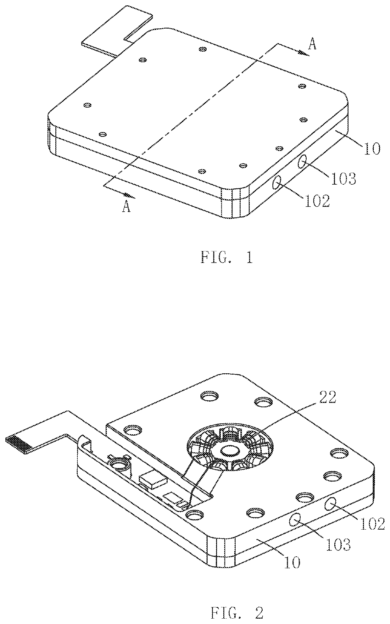
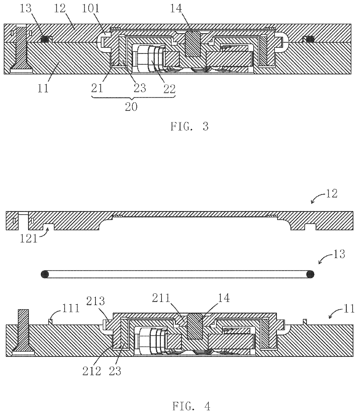
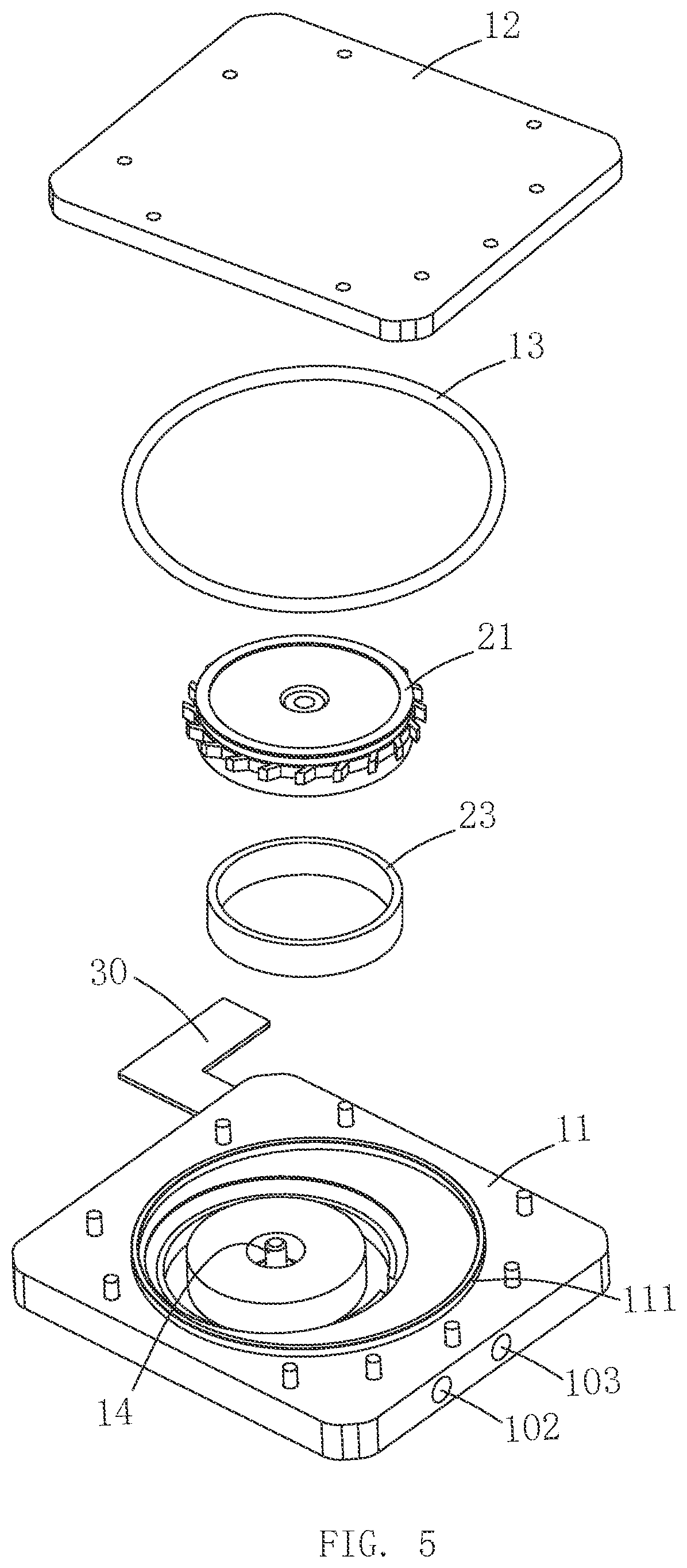
The present invention provides a micro water pump including a pump body provided with an inner cavity, an inlet communicating with the inner cavity, and an outlet communicating with the inner cavity. A drive mechanism is installed on the pump body for driving liquid from the inlet into the inner cavity and discharge from the outlet. The pump body includes a base, an upper cover, and a sealing ring sandwiched between the base and the upper cover. One of the base and the upper cover includes a first circular groove surrounding the inner cavity for arranging the sealing ring; and the other of the base and the upper cover includes at least one circular waterproof step embedded in the first circular groove.

Description

FIELD OF THE PRESENT DISCLOSURE[0001]The present disclosure relates to fluid machinery, in particular to a micro water pump.DESCRIPTION OF RELATED ART[0002]A sealing ring is usually sandwiched between a base and an upper cover of a pump body to achieve sealing. The existing sealing ring between the base and the upper cover of the existing water pump has poor sealing effect and is prone to leakage problems.[0003]Therefore, it is necessary to study a new type of micro water pump to solve the above problems.SUMMARY OF THE PRESENT INVENTION[0004]One of the objects of the present invention is to provide a micro water pump with improved heat-dissipation performance.[0005]To achieve the above-mentioned objects, the present invention provides a micro water pump, comprising: a pump body provided with an inner cavity, an inlet communicating with the inner cavity, and an outlet communicating with the inner cavity; a drive mechanism installed on the pump body for driving liquid from the inlet i...

Claims


Application Information

Patent Timeline
IPC IPC(8): F04D29/42F04D13/06F04D29/08F04D29/22
CPCF04D29/426F04D13/06H05K7/20272F04D29/22F04D29/086F04D29/2222F04D29/242H02K7/14F04D29/628F04D29/406F04D13/0673F04D13/0686H02K5/10
Inventor XU, DETAO
Owner AAC MICROTECH CHANGZHOU
Why Eureka
Try Eureka