
Micro Water Pump

a water pump and micro-chip technology, applied in the field of fluid machinery, can solve the problems of large heat generation of the heating element complicated structure, and affecting the working efficiency of the electronic components of the electronic device, and achieve the effect of improving heat dissipation performan

Inactive Publication Date: 2022-06-02
AAC MICROTECH CHANGZHOU
View PDF11 Cites 0 Cited by
  • Summary
  • Abstract
  • Description
  • Claims
  • Application Information

AI Technical Summary

Benefits of technology

The present invention provides a micro water pump with better heat-dissipation performance.

Problems solved by technology

The heating element of the electronic device generates a large amount of heat during work.
If the heat is not discharged in time, the internal temperature of the electronic device will rise sharply, thereby affecting the working efficiency of the electronic components in the electronic device.
However, a sealing ring needs to be provided between the upper cover and the lower cover to seal the containing space, which is complicated in structure.
The upper cover and the lower cover are fixed by screws and nuts, the number of parts is large, the cost is high, and the assembly is complicated.

Method used


Image

  • Micro Water Pump
  • Micro Water Pump
  • Micro Water Pump

Examples


Embodiment Construction

[0024]The present disclosure will hereinafter be described in detail with reference to exemplary embodiments. To make the technical problems to be solved, technical solutions and beneficial effects of the present disclosure more apparent, the present disclosure is described in further detail together with the figures and the embodiments. It should be understood the specific embodiments described hereby is only to explain the disclosure, not intended to limit the disclosure.

[0025]It should be noted that all directional indicators (such as up, down, left, right, front, back, inside, outside, top, bottom . . . ) in the embodiments of the present invention are only used to explain that they are in a specific posture (As shown in the Fig. below), the relative positional relationship between the components, etc., if the specific posture changes, the directional indication will also change accordingly.

[0026]It should also be noted that when an element is referred to as being “fixed on” or ...


PUM


Abstract

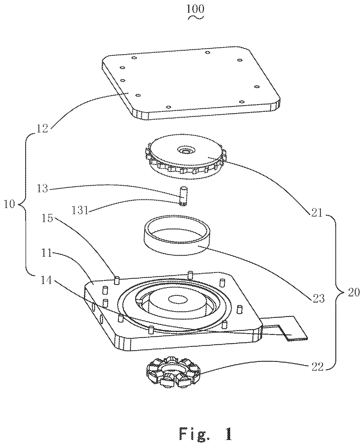
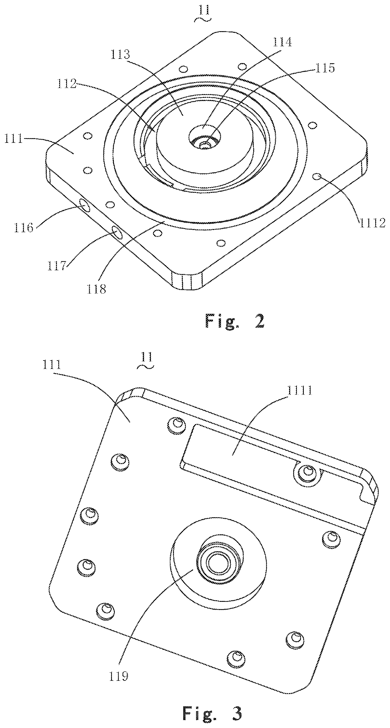
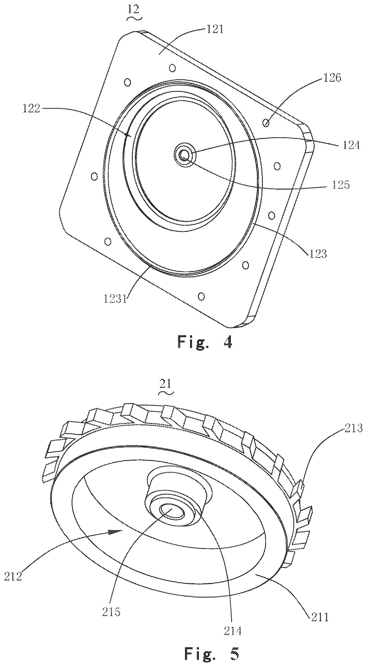
The present disclosure provides a micro water pump, including: a pump body having a cavity, an inlet communicated with the cavity, and an outlet communicated with the cavity; and a drive mechanism engaged with the pump s body for driving liquid from the inlet into the cavity and discharge from the outlet. The pump body includes a base and an upper cover fixed to the base for cooperatively forming the cavity by ultrasonic welding. By virtue of the configuration, improved heat-dissipation performance is performed.

Description

FIELD OF THE PRESENT DISCLOSURE[0001]The present disclosure relates to fluid machinery, in particular to a micro water pump.DESCRIPTION OF RELATED ART[0002]The heating element of the electronic device generates a large amount of heat during work. If the heat is not discharged in time, the internal temperature of the electronic device will rise sharply, thereby affecting the working efficiency of the electronic components in the electronic device. The use of liquid cooling is a better cooling method. The heating element is connected with the cooling pipeline to absorb the heat emitted by the heating element. The coolant flow in the pipeline drains the high-temperature coolant that absorbs heat and replenishes the low-temperature coolant. In order to accelerate the flow of the cooling liquid, a micro water pump is generally connected to the pipeline, and the flow speed of the cooling liquid is accelerated by the micro water pump.[0003]The related technology water pump comprises an upp...

Claims


Application Information

Patent Timeline
Patent Type & Authority Applications(United States)
IPC IPC(8): F04D29/62F04D29/42F04D13/06
CPCF04D29/628F04D13/0693F04D29/426F05D2250/82F04D13/0673F04D29/026F05D2230/232
Inventor XU, DETAOZHANG, QI
Owner AAC MICROTECH CHANGZHOU
Learn More