System, method and controller for graph-based path planning for a host vehicle

Active Publication Date: 2022-06-09
GM GLOBAL TECH OPERATIONS LLC
View PDF6 Cites 0 Cited by
  • Summary
  • Abstract
  • Description
  • Claims
  • Application Information

AI Technical Summary

Benefits of technology

[0011]In the configuration of the controller, the collision potential may be defined by the expression CP=1−{1/[1+e{circumflex over ( )}−(d−DSAFE/2)]}, where CP is the collision potential, d is a respective distance between each projected host vehicle location Li and each projected obstacle location Oi, and DSAFE is a respective predetermined safe threshold distance. The controller may be further configured to execute the step of selecting an optimum sequ

Problems solved by technology

Additionally, each obstacle may b

Method used


Image

  • System, method and controller for graph-based path planning for a host vehicle
  • System, method and controller for graph-based path planning for a host vehicle
  • System, method and controller for graph-based path planning for a host vehicle

Examples


Embodiment Construction

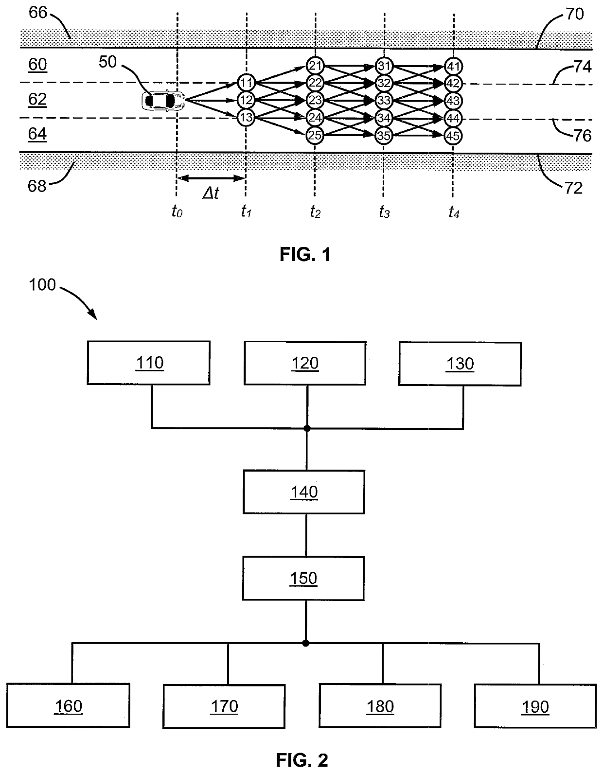
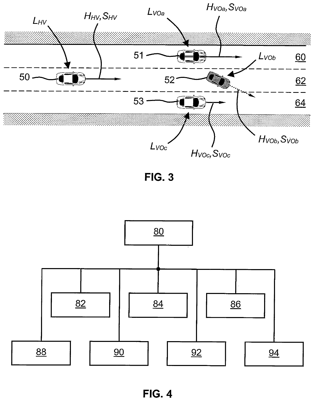
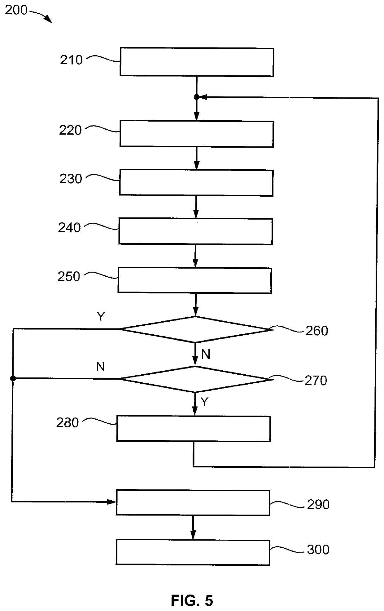
[0020]Referring now to the drawings, wherein like numerals indicate like parts in the several views, a system / controller 100 for graph-based path planning for a host vehicle 50, and a method 200 for graph-based path planning for a host vehicle 50, are shown and described herein. Note that the reference indicators HHV, SHV and LHV in the drawings and specification have the subscript “HV”, which stands for “host vehicle”50, while the indicators HVO, SVO and LVO have the subscript “VO”, which stands for “(other) vehicle / object”51, 52, 53. Further, the “H”, “S” and “L” in these indicators stand for an initial “heading”, initial “speed” or initial “location”, respectively. Also note that the terms “node” and “location” are used interchangeably herein, as each refers to a position or location of a vehicle or object (e.g., on a road surface). Nodes or locations relating to the host vehicle 50 are represented in the drawings by a circle, while nodes or locations of a first, second or third ...


PUM


Abstract

A method of path planning for a host vehicle includes: receiving host vehicle, environmental and obstacle information; calculating one or more projected host vehicle locations; computing a projected obstacle location for each obstacle; and determining a collision potential between each projected host vehicle location and each projected obstacle location. Until a maximum number of steps is reached, and while at least one projected host vehicle location has an associated collision potential below a collision threshold, the method further includes repeating the calculating, computing and determining steps.

Description

INTRODUCTION[0001]This disclosure relates generally to graph-based path planning for host vehicles, and more particularly to systems, methods and controllers for graph-based path planning for host vehicles.[0002]Autonomous and semi-autonomous vehicles (such as drones, robots and automotive vehicles) may be guided along paths or trajectories by various methods. One such method is known as graph-based path planning. In this method, the current and possible future locations of the vehicle are determined for a short timeframe, such as for the next 0.5 to 5 seconds. The method uses an approach similar to plotting out the locations on a graph or grid, where the environment—such as roads, lanes, airspace, other vehicles or obstacles, etc.—are also represented on the graph or grid. This approach may be carried out by on-board systems or controllers, or by off-board systems to which the vehicle has wireless or other remote access, and the determination of possible future locations for the ve...

Claims


Application Information

Patent Timeline
IPC IPC(8): B60W60/00G05D1/02
CPCB60W60/0027G05D2201/0213B60W2554/4044B60W2554/4042B60W2554/4043B60W2554/4041B60W2520/10B60W2520/12B60W2552/10B60W2552/20B60W2555/60B60W2555/20B60W2554/804B60W2554/802B60W2554/801B60W2554/803G05D1/0214G05D1/0223G05D2201/0212B60W60/0011B60W60/00272B60W2754/10
Inventor KULKARNI, DIVYA P.KWON, HYUKSEONGYAMADA, KENJIHWU, TIFFANY J.KIM, KYUNGNAMBHATTACHARYYA, RAJANDAILY, MICHAEL J.
Owner GM GLOBAL TECH OPERATIONS LLC
Why Eureka
Try Eureka