
Rational z-buffer for decreasing a likelihood of z-buffer collisions

a z-buffer and probability technology, applied in the field of z-buffer, can solve the problems of individual pixels' visible artifacts in images, and achieve the effect of greatly reducing the probability of z-buffer collision, significantly reducing the resultant artifacts, and reducing the likelihood of z-buffer collision

Inactive Publication Date: 2009-12-31
MICROSOFT TECH LICENSING LLC
View PDF14 Cites 3 Cited by
  • Summary
  • Abstract
  • Description
  • Claims
  • Application Information

AI Technical Summary

Benefits of technology

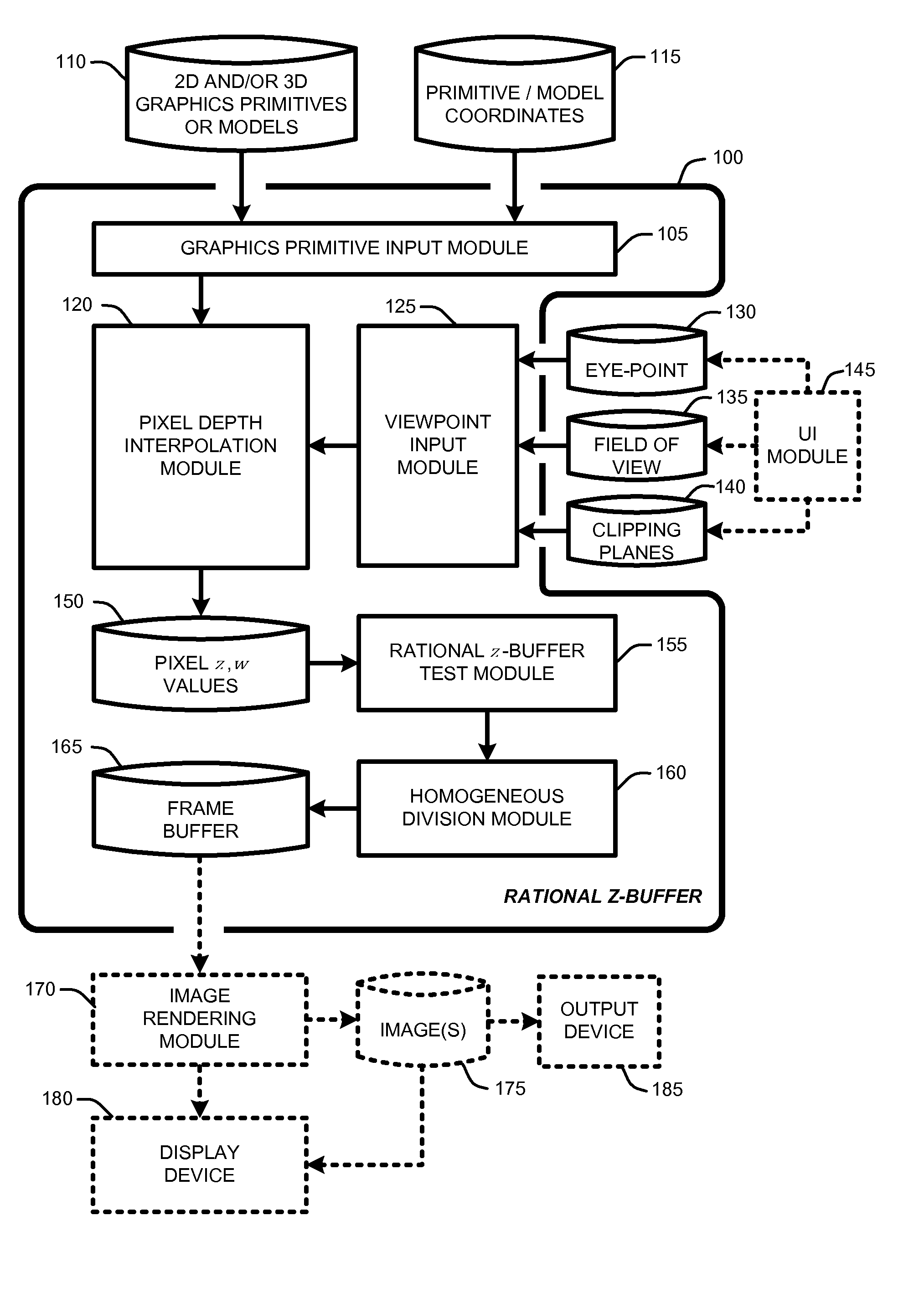
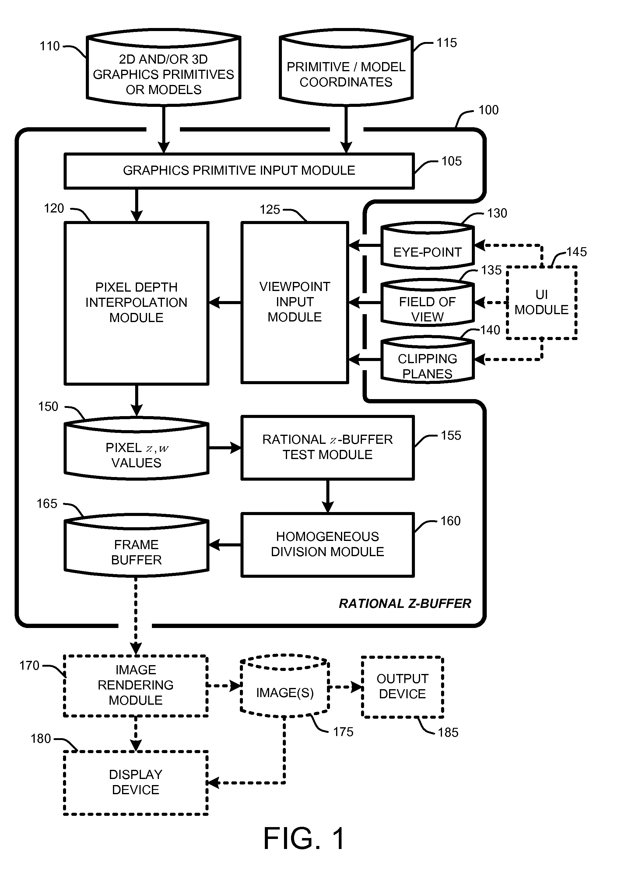
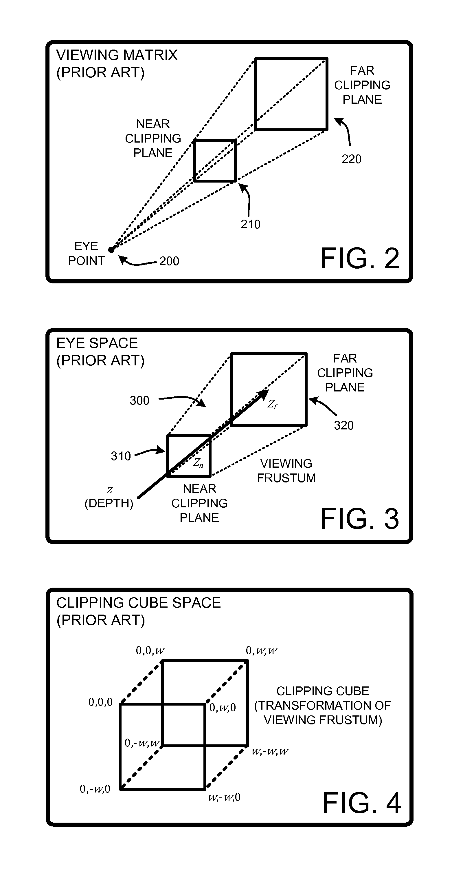
[0012]In other words, the Rational Z-Buffer stores both z and w components of a pixel's clipping cube space coordinates in a depth buffer. These coordinates are then used to replacing the conventional z-buffer test (i.e., z0<z1) with a “rational z-buffer test” z0w1<z1w0. Non-occluded pixels are then provided to a frame buffer and rendered using conventional rendering techniques. Note that in clipping-cube space, since both z and w are linear in eye-space z, these values are uniformly distributed in the rational z-buffer. As a result, potential z collisions are greatly reduced relative to conventional z-buffer testing, thereby significantly reducing artifacts resulting from z collisions.
[0013]In view of the above summary, it is clear that the Rational Z-Buffer described herein provides various unique techniques for reducing the likelihood of z-buffer collisions when using hardware or software z-buffer algorithms to render graphics. In addition to the just described benefits, other advantages of the Rational Z-Buffer will become apparent from the detailed description that follows hereinafter when taken in conjunction with the accompanying drawing figures.

Problems solved by technology

Unfortunately, one of the problems with the use of conventional z-buffer algorithms is that since z-buffers represent numbers with finite precision, it is often the case that distinct depth values for different pixels map to the same values when rendering images using z-buffers.
This type of z-buffer collision often causes visible artifacts in images at the level of individual pixels.

Method used


Image

  • Rational z-buffer for decreasing a likelihood of z-buffer collisions
  • Rational z-buffer for decreasing a likelihood of z-buffer collisions
  • Rational z-buffer for decreasing a likelihood of z-buffer collisions

Examples


Embodiment Construction

[0022]In the following description of the embodiments of the claimed subject matter, reference is made to the accompanying drawings, which form a part hereof, and in which is shown by way of illustration specific embodiments in which the claimed subject matter may be practiced. It should be understood that other embodiments may be utilized and structural changes may be made without departing from the scope of the presently claimed subject matter.

[0023]1.0 Introduction:

[0024]In general, a “Rational Z-Buffer” as described herein, first determines corresponding z and w values by evaluating a linear equation in x and y for each pixel at screen position, x y. The linear equations have the property that vertices are interpolated. These interpolated depth values are subject to the same non-uniform distribution in clipping-cube space as vertices.

[0025]Further, instead of storing a single values corresponding to the result of the division z / w (as with conventional z-buffer testing), the Rati...


PUM


Abstract

A “Rational Z-Buffer” provides various techniques for reducing artifacts when rendering graphics using z-buffers. In particular, the Rational Z-Buffer reduces the likelihood of z-buffer collisions when using hardware or software z-buffer algorithms to render graphics by delaying homogenous division of pixels until after occlusion testing. Further, occlusion testing between any two pixels, p0 and p1, is accomplished by comparing rational depth values, r0={z0, w0} and r1={z1, w1}, for pixel p0 and p1 to determine which pixels are visible. Depth values are compared by determining whether the expression z0w1<z1w0 is true. If true, then pixel p0 occludes pixel p1 in clipping cube space relative to an image-plane defined by a particular viewpoint and the field of view. Further, since homogeneous division by w is not performed prior to occlusion testing, rational depth values are uniformly distributed clipping-cube space, thereby significantly reducing potential z collisions relative to conventional z-buffer testing.

Description

BACKGROUND[0001]1. Technical Field[0002]A “Rational Z-Buffer” provides techniques for reducing artifacts when rendering graphics using z-buffers, and in particular, various techniques for reducing the likelihood of z-buffer collisions when using hardware or software z-buffer algorithms to render graphics.[0003]2. Related Art[0004]As is well known to those skilled in the art, the z-buffer algorithm is the most common technique for displaying only the visible portions of a scene in 3D computer graphics applications. It is generally implemented in graphics hardware, though software-only implementations can be used as well. The term z-buffer refers to an array of numbers whose dimensions correspond to the pixel array of an image, or frame-buffer, to be rendered. The computer representation of these numbers varies; they are typically 16- or 32-bit integer or floating point, but can be any size desired, depending upon the available graphics hardware or software.[0005]The imaging model use...

Claims


Application Information

Patent Timeline
Patent Type & Authority Applications(United States)
IPC IPC(8): G06T15/40
CPCG06T15/405
Inventor LOOP, CHARLES T.
Owner MICROSOFT TECH LICENSING LLC
Learn More