Electron spin resonance microscope for imaging with micron resolution

a micron resolution, electron spin resonance technology, applied in the field of high resolution electron spin resonance (esr) imaging, can solve the problems of difficult image accuracy, inconclusive clinical diagnosis of histological samples, inability to observe moderately thick three-dimensional (3d) non-transparent samples, etc., to improve the snr, reduce artifacts, and improve the effect of permittivity

Inactive Publication Date: 2008-07-22
CORNELL RES FOUNDATION INC
View PDF17 Cites 114 Cited by
  • Summary
  • Abstract
  • Description
  • Claims
  • Application Information

AI Technical Summary

Benefits of technology

[0023]In one embodiment, the resonator material possesses at least one of the following unique features and advantages for ESR microscopy: a high concentration of electromagnetic [EM] field by high-permittivity dielectric (thereby yielding a high SNR and a small “effective volume” from which the signal is obtained); a proportional concentration of B1 field and correspondingly reduced r.f. (radio-frequency / microwave) input power; a proportional reduction of power dissipation in gradient and modulation coils; a smaller resonator and consequently reduction in the requirement for the volume of homogenous B0, which allows the use of a smaller primary magnet; a minimized resonator volume that alternately permits the use of a permanent magnet assembly (with vernier scan coils) for the B0 field; a non-conducting dielectric ring structure that is inherently immune to eddy current effects. In one embodiment, the construction features facilitate specimen insertion and manipulation (e.g., for precise positional adjustment of high permittivity bio-samples). In one embodiment, the open design permits unimpeded gas flow for temperature stabilization of resonator (for controlled-temperature experiments and removal of heat generated in gradient and modulation coils). In one embodiment, the microwave coupling scheme utilizes microstrip or thin coaxial antenna to obtain high coupling coefficient in limited space without introduction of a deleterious metallic ground plane in sensitive regions (which can cause the reduction of the resonator Q or enable Eddy currents that disturb the magnetic field near the sample). Coupling may also be achieved through the use of a dielectric waveguide antenna. Such an antenna allows the elimination of any metallic parts in the vicinity of the resonator and consequently provides better immunity to eddy currents effects that may arise due to the pulsed field gradients.
[0027]Other exemplary features of the invention that are believed to be significant include: the possibility in CW mode of varying the phase and or frequency of the excitation of the gradient coils during the integration time to improve the SNR and / or to reduce artifacts; the use of high permittivity material with low losses as components of the imaging probe; the ability to position samples in a millimeter-sized resonator to accuracies of 50 to 100 microns (and proportionally more accurately as the resonator size is reduced); the use of automatically controlled or computer controlled (as compared to manually controlled) high gain amplifiers in baseband amplifier and filtering units; the possibility of using temperature shift at the resonator for tuning the resonance frequency; and the use of many generally known deconvolution methods, and associated computer programs or software modules for obtaining images in the projection reconstruction method.
[0028]In some embodiments, data obtained from the use of the ESR microscope may be combined with confocal optical and / or fluorescence microscopy data to provide better assignment of the image and more complete information about the imaged object.

Problems solved by technology

Nevertheless, such optical-based modalities lack the ability to observe moderately thick three-dimensional (3D) non-transparent samples.
They can not measure vital parameters such as molecular self diffusion and 3D flow vectors, and, for example in terms of medical tissues, many times result in inconclusive clinical diagnosis of histological samples.
Furthermore, using optical methods, the following difficulties are encountered: it is difficult to image accurately the O2 partial pressure in specimens; it is difficult to recognize with high specificity various superoxides in the imaged sample; one can not measure a variety of image contrasts such as the spatially-resolved magnetic resonance relaxation times (T1 and T2) and the lineshape of the spins in the sample; and optical methods lack the possibility to correlate in-vitro with in-vivo measurements.
The main drawback of the existing NMR microscopes is their high price (in the range of $500,000 to $1,500,000, mainly due to the superconducting magnet technology required for their operation), and the limited image resolution they offer (>10 microns), which can not rival the <0.5 micron resolution of optical imaging modalities.
Due to these limitations (and regardless of the many potential advantages), the full potential of magnetic resonance microscopy cannot be readily exploited and such instruments are presently much less abundant than the optical-based microscopes in scientific and medical laboratories around the world.
Such experiments, conducted in-vivo, employ low fields of ˜10 mT at low RF frequencies (which results in relatively low spin sensitivity), so that the RF energy will penetrate deeply into the relatively large biological object.
Such high permittivity small resonator structures, however, were not employed in the past as a basis for a miniature ESR imaging probe (which includes a resonator and the imaging gradient coils).
Nevertheless all these methods can be employed only to a very limited extent when botanically and biologically-related or relatively thick samples are considered.
Thus, for example, the detection by magnetic tips as described in U.S. Pat. No. 6,683,451 suffers from low 3D sensitivity, especially when the samples are thicker than a few microns.
Furthermore, this technique requires extreme physical conditions (high vacuum and often low temperatures), and can be employed only after complicated sample preparation.
The Hall detection and the miniature microwave scanning probe methods also operates only on the surface, or slightly below it, and have not proven to be useful in micron resolution imaging.
A number of problems in nuclear magnetic resonance imaging have been observed, including the need for strong magnetic fields, requiring expensive superconducting magnets, and the limited spatial resolution of images that are obtained.

Method used


Image

  • Electron spin resonance microscope for imaging with micron resolution
  • Electron spin resonance microscope for imaging with micron resolution
  • Electron spin resonance microscope for imaging with micron resolution

Examples


Embodiment Construction

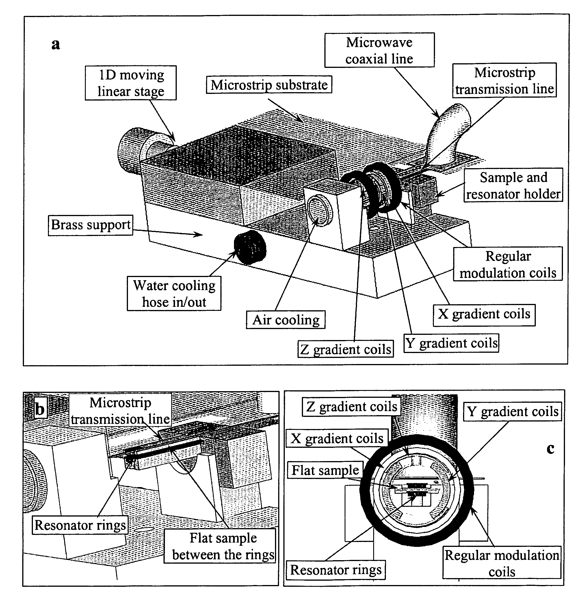
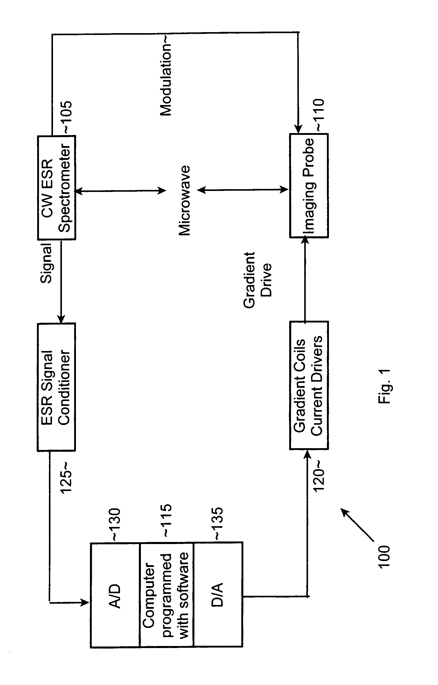
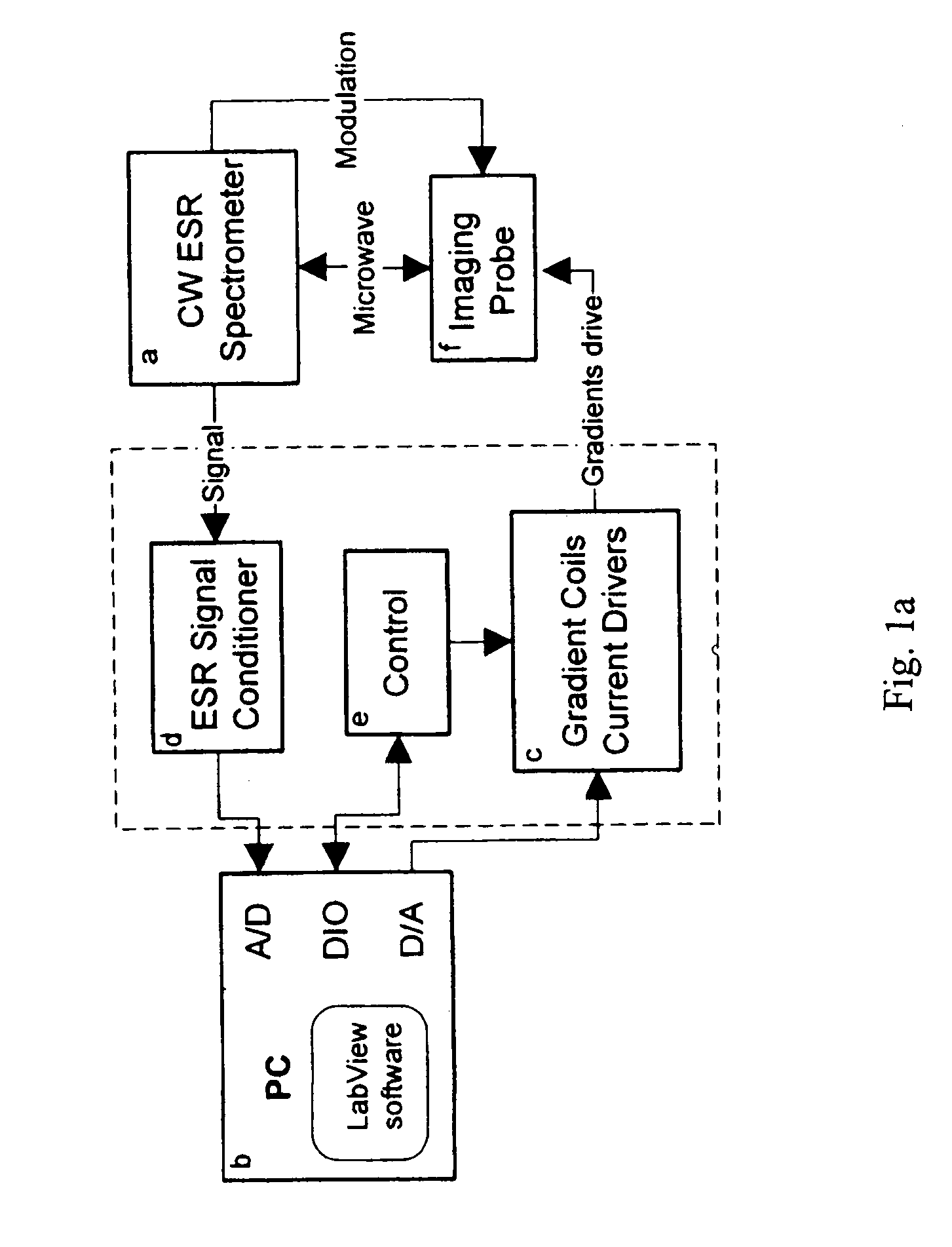
[0045]An Electron-Spin Resonance [ESR] (also referred to as Electron-Paramagnetic Resonance [EPR]) microscope is described, and methods of use of the microscope are presented. This imaging system overcomes the resolution limitations of existing NMR-based magnetic resonance microscopy and provides complimentary 3D information to optical microscopy, in a sub-micron resolution. The ESR microscope may be realized as a compact stand-alone instrument or as a retrofit compatible with existing ESR spectrometer instruments. Two distinct means of obtaining ESR micro-images, based on continuous-wave [CW] and pulsed signal acquisition methods, are possible with minor variation of the ESR microscope invention. As used in this application, the term “image” and its variants (e.g., images, imaging, and so forth, whether used as a noun or as a verb) refer to spatially resolved (1D, 2D, or 3D) information that can be obtained about the examined sample, or the act of obtaining such information, using ...


PUM


Abstract

ESR microscope systems and methods for examining specimens using both continuous wave and pulsed modes in the 9 to 60 GHz range. The ESR microscope uses an image probe comprising gradient coils in addition to conventional modulation coils (in continuous wave mode) or magnetic field bias coils (in pulse mode), and a resonator constructed from high permittivity material. The systems and methods also involves the use of sample containers that permit the precise placement of samples in relation to the image probe. The microscope uses a microstrip or thin coaxial or dielectric antenna to obtain a high coupling coefficient to the specimen being imaged. The microscope systems provide resolution at the single micron level, and permit the observation of images comprising tens to hundreds of pixels for each of two or three dimensions in a few minutes. Novel stable radicals used as the imaging media are also described.

Description

CROSS-REFERENCE TO RELATED APPLICATIONS[0001]This application claims priority to and the benefit of co-pending U.S. provisional patent application Ser. No. 60 / 598,100, filed Aug. 2, 2004, which application is incorporated herein by reference in its entirety.STATEMENT REGARDING FEDERALLY SPONSORED RESEARCH OR DEVELOPMENT[0002]This invention was made with Government support from the National Science Foundation (NSF) under Grant No. CHE0098022. The Government has certain rights in the invention.FIELD OF THE INVENTION[0003]The invention relates to magnetic resonance imaging in general and particularly to high resolution electron spin resonance (ESR) imaging.BACKGROUND OF THE INVENTION[0004]Many fields of science and medicine require the close observation of small samples, for example, thin tissue slices extracted from living organisms or living / fixed cell cultures. Currently, the leading modalities for these kinds of observations are optical and fluorescence microscopy. These techniques...

Claims


Application Information

Patent Timeline
Patent Type & Authority Patents(United States)
IPC IPC(8): G01V3/00
CPCG01R33/60
Inventor BLANK, AHARONDUNNAM, CURT R.BORBAT, PETER P.FREED, JACK H.
Owner CORNELL RES FOUNDATION INC
Why Eureka
Try Eureka