Mobile Water Delivery Device

a mobile, water-delivering technology, applied in waterborne vessels, special-purpose vessels, vehicles, etc., can solve the problems of limited movement of fixed water-delivering devices, limited visual effects they can produce, and inability to provide appearance, so as to dampen the effect of the force applied and add additional stability to the boa

Pending Publication Date: 2019-03-28
FULLER MARK W +1
View PDF11 Cites 2 Cited by
  • Summary
  • Abstract
  • Description
  • Claims
  • Application Information

AI Technical Summary

Benefits of technology

[0015]Another aspect of the current invention involves the use of a gyroscope with the boat to add additional stability to the boat as it moves about the reservoir emitting water streams.
[0016]Yet another aspect of the invention involves the use of keels or reaction plates on the boat to counteract the forces applied to the boat due to the emission of water streams. In this way, the viscous drag of the water on the reaction plates may dampen effects of the forces applied.
[0019]Another aspect of the invention involves a multitude of water delivery devices and / or water vehicles moving about the reservoir in unison and in a choreographed fashion. In this manner, the current invention may enhance the overall visual effects of the display.
[0021]Another aspect of the current invention involves a collision detection and avoidance system such that potential collisions between different vehicles may be avoided.

Problems solved by technology

These existing water delivery devices may provide dramatic visual effects, but if they are fixed to the bottom of the water reservoir, there is some limitation of the visual effects they can produce.
For example, fixed water delivery devices typically cannot provide the appearance of a stream of water that moves to different locations in the reservoir.
In these cases, the water delivery devices may indeed move about, but may be limited to moving along the predefined tracks and are thus somewhat limited in their available movement.

Method used


Image

  • Mobile Water Delivery Device
  • Mobile Water Delivery Device
  • Mobile Water Delivery Device

Examples


Embodiment Construction

[0038]The following detailed description is not intended to limit the current invention. Alternate embodiments and variations of the subject matter described herein will be apparent to those skilled in the art.

[0039]The display 10 of the current invention and the visual effects that it may produce are now described with reference to the figures. Where the same or similar components appear in more than one figure, they are identified by the same or similar reference numerals.

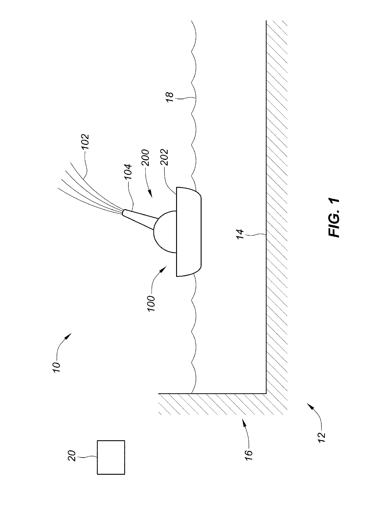
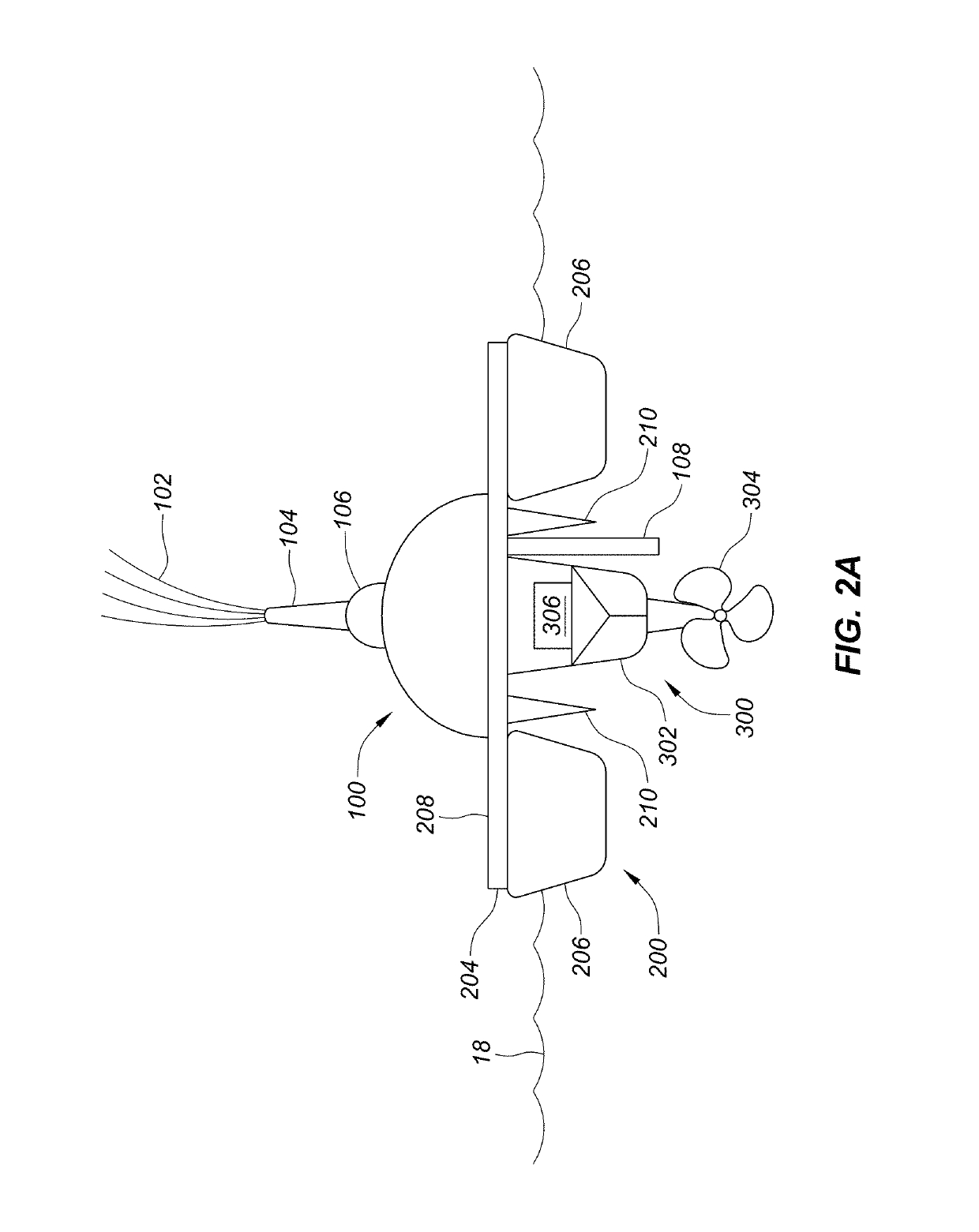
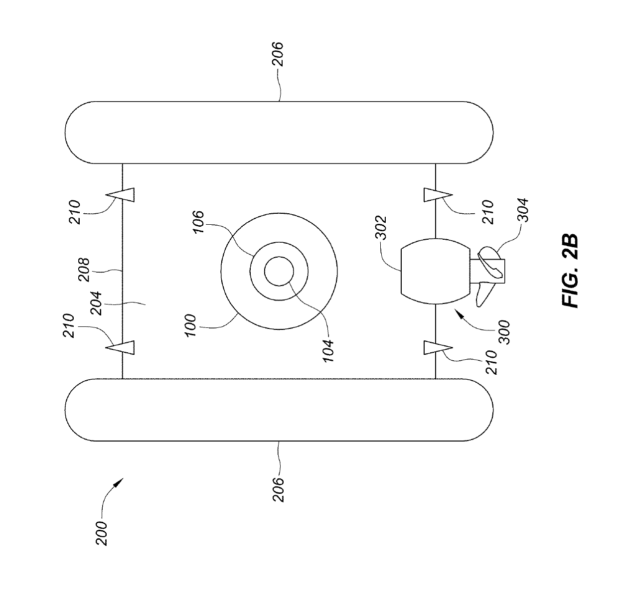
[0040]In general, display 10 provides dramatic visual effects by including one or more water delivery devices 100 that may move about within a pool or reservoir 12 while emitting choreographed water streams. Display 10 may be installed or located near hotels, restaurants or public buildings, or in gardens, parks or amusement areas, or poolside or in other types of outdoor spaces. In addition, display 10 may also be installed within atriums, lobbies or in other indoor locations. As such, display 10 may provide an ...


PUM


Abstract

A device to move and control a water shooter is described. The device may contain features that allow the device to travel along the surface of a reservoir with a water shooter attached. The device may be free from a physical connection to the bottom or the sides of the reservoir so that unique water effects may be achieved.

Description

CROSS-REFERENCE TO RELATED APPLICATION[0001]This application claims the benefit of U.S. Provisional Application No. 62 / 561,162, filed Sep. 20, 2017, the contents of which are incorporated herein by reference.FIELD OF THE INVENTION[0002]The current invention generally relates to water delivery devices that provide a stream of water, including devices that emit water streams as they move around a body of water. The current invention also relates to the use of such devices with fountain and lighting displays.BACKGROUND OF THE INVENTION[0003]Various types of water displays exist, and many of them include water delivery devices that emit streams of water. Oftentimes, the water display is located in a reservoir having a floor and walls. Before the reservoir is filled with water, a network of water delivery devices may be attached to the bottom of the reservoir in a variety of formations. This network may include the water delivery devices themselves, as well as supporting lines such as el...

Claims


Application Information

Patent Timeline
Patent Type & Authority Applications(United States)
IPC IPC(8): B05B17/08
CPCB05B17/08B05B12/06B63B35/00
Inventor FULLER, MARK W.DOYLE, JAMES W.
Owner FULLER MARK W
Why Eureka
Try Eureka