
Tire

a technology of tires and treads, applied in the field of tires, can solve the problems of insufficient traction of tires and snowy roads, and achieve the effects of reducing the noise of tire pattern, sufficient traction of tires, and considering the living environmen

Pending Publication Date: 2022-06-16
SUMITOMO RUBBER IND LTD
View PDF0 Cites 0 Cited by
  • Summary
  • Abstract
  • Description
  • Claims
  • Application Information

AI Technical Summary

Benefits of technology

The patent aims to provide a tire that can reduce pattern noise while maintaining traction on snowy roads. The technical effect of the patent is to improve the comfort and safety of the tire's living environment while ensuring sufficient traction on snow-covered roads.

Problems solved by technology

In addition, sufficient traction of tires is also required on snowy roads.

Method used


Image

  • Tire
  • Tire
  • Tire

Examples


example

Example A

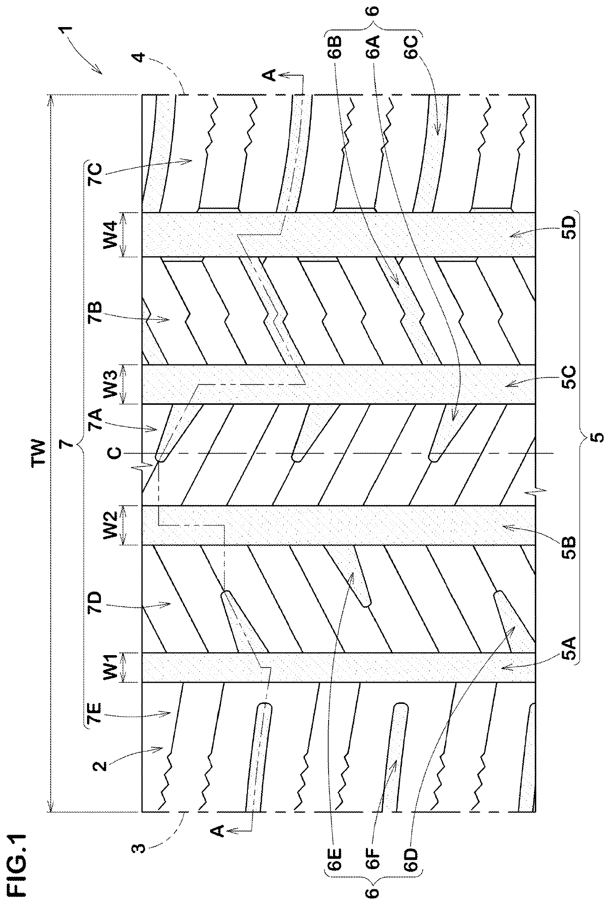
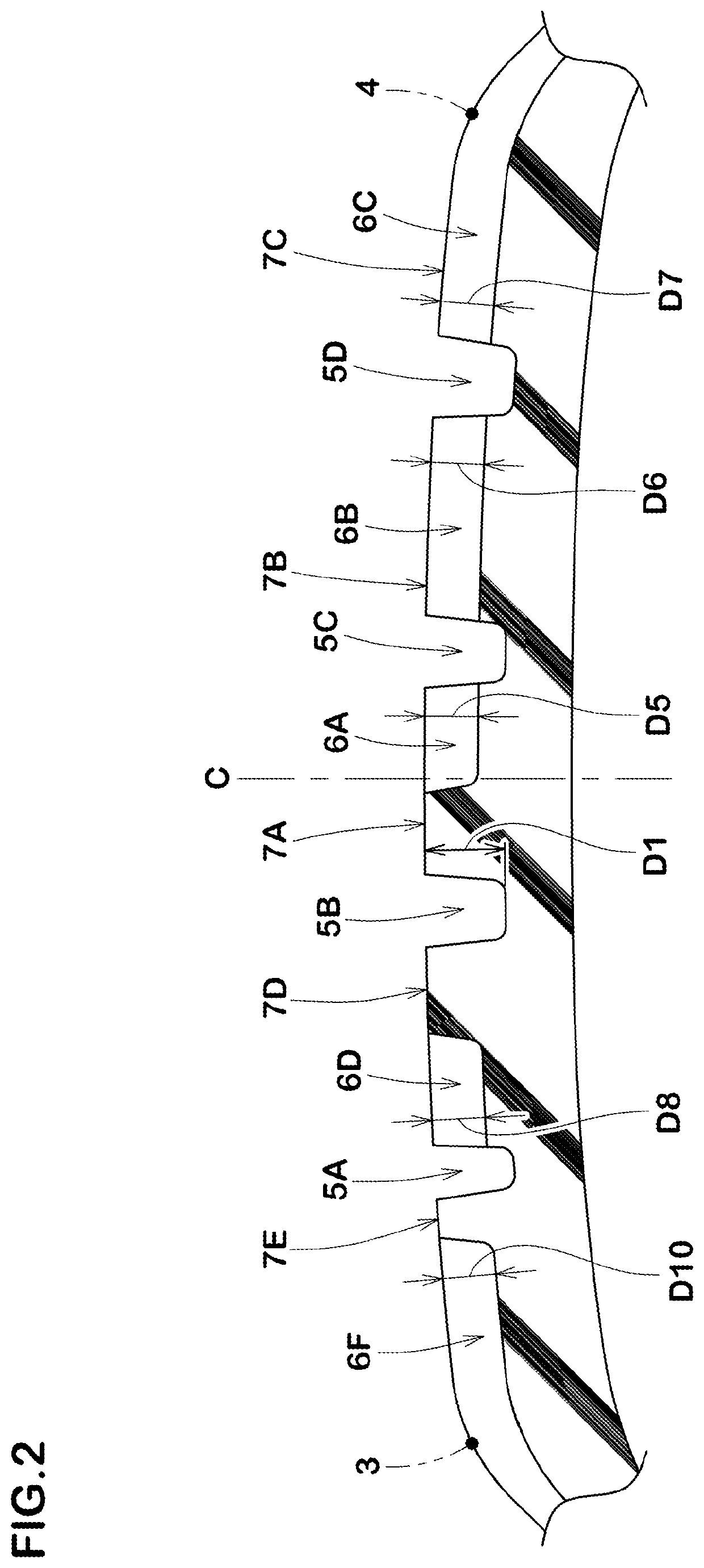
[0099]Tires (Examples 1 to 4) having the basic structure shown in FIG. 1 were prototyped based on the details shown in Table 1. The tires have the groove widths W1, W2, W3 and W4 of the outside shoulder circumferential groove, the outside crown circumferential groove, the inside crown circumferential groove and the inside shoulder circumferential groove, respectively, satisfying the following relation:

W1

[0100]For comparison, as illustrated in FIG. 6A, a tire whose groove widths satisfy the relation of “W1=W2=W3=W4” (Comparative Example 1), and as illustrated in FIG. 6B, a tire whose groove widths satisfy the relation of “W2=W3>W1=W4” (Comparative Example 2) were also prototyped.

[0101]Then, pattern noise and snow traction were evaluated for each prototype tire. The common specifications and test methods are as follows. The test results are shown in Table 1.[0102]Tire size: 225 / 65R17[0103]Rim size: 17×6.5J[0104]Inner pressure: 230 kPa[0105]Test vehicle: four-wheel-d...

example b

[0117]Tires (Examples 1 and 5 to 12) having the basic structure shown in FIG. 1 were prototyped based on the details shown in Table 2. The tires have the groove widths W1, W2, W3 and W4 of the outside shoulder circumferential groove, the outside crown circumferential groove, the inside crown circumferential groove and the inside shoulder circumferential groove, respectively, satisfying the following relation:

W1

[0118]The test results are shown in Table 2. The common specifications are the same as in Example A, except for the specifications in Table 2.

TABLE 2Ex. 5Ex. 6Ex. 1Ex. 7Ex. 8Ex. 9Ex. 10Ex. 11Ex. 12(Total value of maximum groove widths of253035404535353535crown lateral grooves + total value of maximumgroove widths of inside middle lateral grooves) / circumferential length of tread portion (%)(Total value of maximum groove widths of252525252518203032inside shoulder lateral grooves + total value ofmaximum groove widths of inside middlelateral grooves) / circumferential leng...

example c

[0120]Tires (Examples 1 and 13 to 20) having the basic structure shown in FIG. 1 were prototyped based on the details shown in Table 3. The tires have the groove widths W1, W2, W3 and W4 of the outside shoulder circumferential groove, the outside crown circumferential groove, the inside crown circumferential groove and the inside shoulder circumferential groove, respectively, satisfying the following relation:


PUM


Abstract

A tire includes a tread portion including an outside tread edge located outwardly of a vehicle when being mounted to the vehicle, an inside tread edge located inwardly of a vehicle when being mounted to the vehicle, circumferential grooves extending continuously in the tire circumferential direction, and lateral grooves. The circumferential grooves includes an outside shoulder circumferential groove, an outside crown circumferential groove, an inside crown circumferential groove and an inside shoulder circumferential groove which are arranged in this order from the outside tread edge side to the inside tread edge side, and a groove width W1 of the outside shoulder circumferential groove, a groove width W2 of the outside crown circumferential groove, a groove width W3 of the inside crown circumferential groove and a groove width W4 of the inside shoulder circumferential groove satisfy the following relation: W1<W2<W3<W4.

Description

RELATED APPLICATIONS[0001]This application claims the benefit of foreign priority to Japanese Patent Application No. JP2020-208703, filed Dec. 16, 2020, which is incorporated by reference in its entirety.FIELD OF THE INVENTION[0002]The present disclosure relates to a tire.BACKGROUND OF THE INVENTION[0003]The following Patent Document 1 discloses a pneumatic tire. The tire includes a tread portion which is provided with center main grooves extending continuously in the tire circumferential direction on the tire equator side and shoulder main grooves extending continuously in the tire circumferential direction located on the tread edge sides with respect to the center grooves.[Patent Document][0004][Patent document 1] Japanese Unexamined Patent Application Publication 2012-224245SUMMARY OF THE INVENTION[0005]In recent years, consideration for the living environment has been emphasized, and reduction of pattern noise of tires is desired. In addition, sufficient traction of tires is als...

Claims


Application Information

Patent Timeline
Patent Type & Authority Applications(United States)
IPC IPC(8): B60C11/03
CPCB60C11/0302B60C11/0304B60C2011/0353B60C11/033B60C11/0306B60C11/03B60C2011/0358B60C2011/0388B60C2011/0381B60C2011/0383B60C2011/1209B60C2011/1213B60C2011/0365
Inventor NAKANO, KAZUHIRO
Owner SUMITOMO RUBBER IND LTD
Learn More