Stacked rolling shutter and global shutter image sensor with knee self point calibration

Active Publication Date: 2019-04-02
SMARTSENS TECH (HK) CO LTD
View PDF2 Cites 9 Cited by
  • Summary
  • Abstract
  • Description
  • Claims
  • Application Information

AI Technical Summary

Benefits of technology

[0015]A further objective of the present invention is to provide an apparatus and a method for reducing fixed pattern noise related to variations among image sensor p

Problems solved by technology

However, miniaturization has come with the loss of pixel photosensitivity and dynamic range which require new approaches in order to mitigate these losses.
A potential disadvantage of rolling shutter readout mode is spatial distortion which may result from the above.
Another disadvantage is that different regions of the exposed image will not be precisely correlated in time and may appear as a distortion in the image.
However it carries risk of spatial distortion es

Method used


Image

  • Stacked rolling shutter and global shutter image sensor with knee self point calibration
  • Stacked rolling shutter and global shutter image sensor with knee self point calibration
  • Stacked rolling shutter and global shutter image sensor with knee self point calibration

Examples


first embodiment

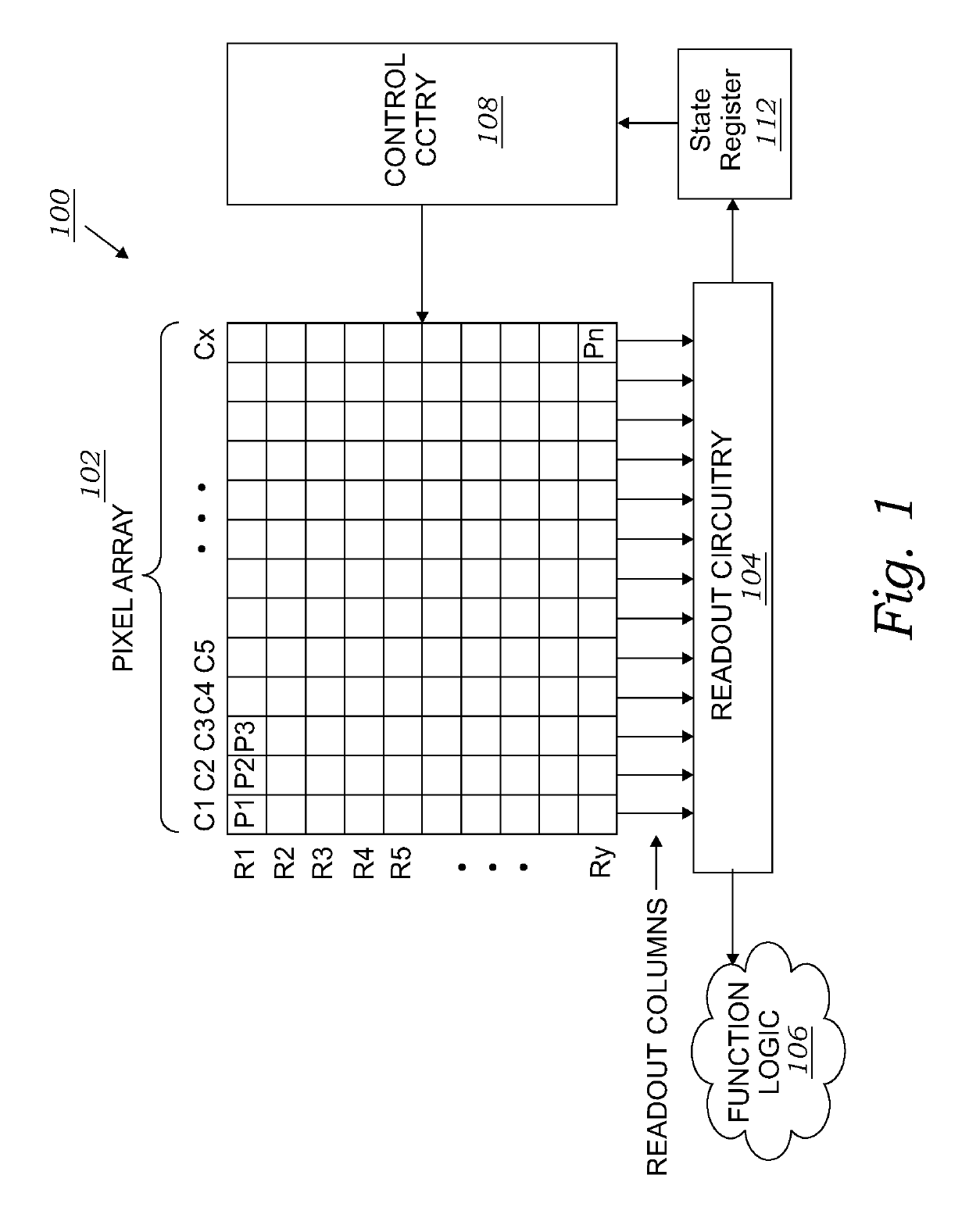
[0035]FIG. 1 is a diagram illustrating an image sensor system 100 (“imaging system”) including a pixel array 102 having a plurality of image sensor pixels included in an example integrated circuit system with features in accordance with the teachings of the present invention. As shown in the depicted example, in the imaging system 100, the pixel array 102 is coupled to control circuitry 108 and readout circuitry 104, which is coupled to function logic 106.

[0036]The control circuitry 108 may include a row decoder and a row driver with required timing circuits while readout circuitry 104 may include a column decoder and a column driver with required timing circuits. The control circuitry 108 and the readout circuitry 104 are also coupled to state register 112. In one example, the pixel array 102 is a two-dimensional (2D) array of image sensor pixels (e.g., pixels P1, P2 . . . , Pn). As illustrated, each pixel is arranged into a row (e.g., rows R1 to Ry) and a column (e.g., column C1 t...


PUM


Abstract

An image sensor has a stacked pixel arrangement including both rolling and global shutter readout circuits wherein each pixel includes an adjustable transfer transistor gate voltage level for modifying electric charge within a photodiode during exposure depending on incident light intensity. The sensor also has a row decoder circuit providing readout signals to each row of the imaging cells during both a readout interval and during a calibration interval for each row. The row decoder may employ one of several of its features to provide a self-knee point calibration following an image signal readout in order to minimize photo conversion variations that lead to fixed pattern noise and to enhance dynamic range.

Description

BACKGROUND OF THE INVENTIONField of the Invention[0001]This invention relates generally to image sensors, and more particularly to CMOS image sensors in a stacked chip formation. The bottom chip includes an array of light sensitive regions and structures to capture an image. The top chip includes circuit elements to extract an image from the array. The image sensor may be incorporated within a digital camera.Description of Related Art[0002]An image capture device includes an image sensor and an imaging lens. The imaging lens focuses light onto the image sensor to form an image, and the image sensor converts the light into electrical signals. The electric signals are output from the image capture device to other components of a host electronic system. The image capture device and the other components of a host electronic system form an imaging system. Image sensors have become ubiquitous and may be found in a variety of electronic systems, for example, a mobile device, a digital came...

Claims


Application Information

Patent Timeline
IPC IPC(8): H04N5/3745H04N5/361H04N5/378H04N5/372H04N5/363
CPCH04N5/363H04N5/37213H04N5/37457H04N5/378H04N5/361H04N25/575H04N25/778H04N25/77H04N25/79H04N25/63H04N25/65H04N25/75H04N25/713
Inventor XU, CHENMO, YAOWUSHAO, ZEXUZHANG, ZHENGMINMA, WEIJIAN
Owner SMARTSENS TECH (HK) CO LTD
Why Eureka
Try Eureka