
Electromechanical switching device of an electric power circuit

a technology of electric power circuit and switching device, which is applied in the direction of protective switch operating/release mechanism, relay, transportation and packaging, etc., can solve the problems of partial or total degradation of the circuit and the solution is not optimal

Active Publication Date: 2022-06-16
AIRBUS OPERATIONS (SAS)
View PDF4 Cites 0 Cited by
  • Summary
  • Abstract
  • Description
  • Claims
  • Application Information

AI Technical Summary

Benefits of technology

The invention prevents a spurt in the main breaker when there are high short-circuit currents. It does this by increasing the force generated by the actuator when a current sensor detects a current higher than a certain level. The invention also allows for control of the time it takes for the control signal to return to its original level, making it easier to control the system.

Problems solved by technology

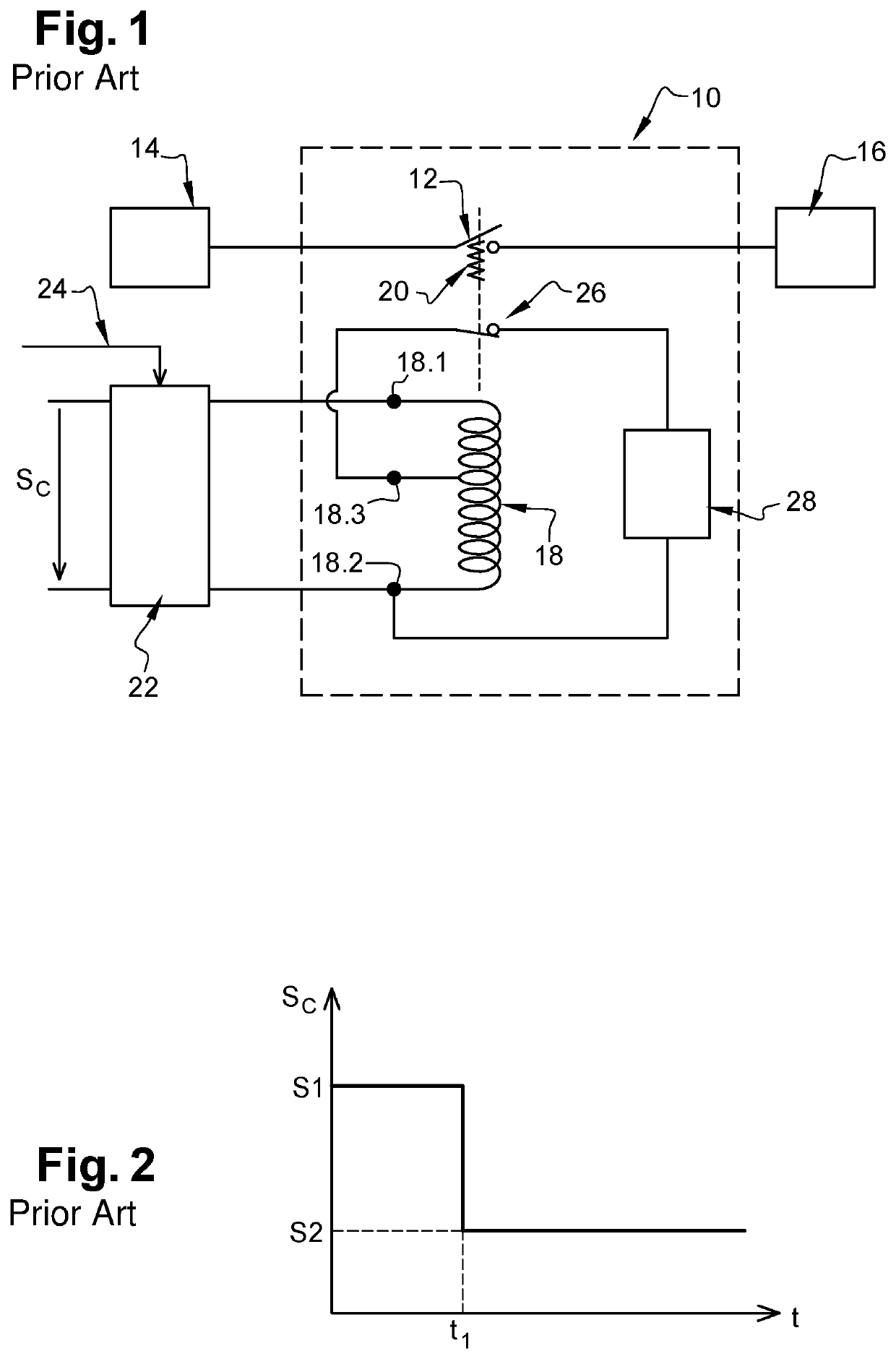
This unwanted opening of the main breaker 12 causes electric arcs which may lead to its partial or total degradation.
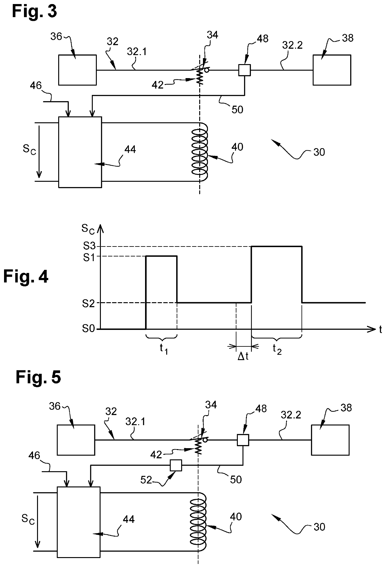
However, this solution is not optimal since the passage from the second level to the third level and the time during which the control signal is held at the third level are not optimized.

Method used


Image

  • Electromechanical switching device of an electric power circuit
  • Electromechanical switching device of an electric power circuit

Examples


Embodiment Construction

[0033]In FIG. 3, a switching device 30 for a power electrical circuit 32 comprises at least one main breaker 34 together with an upstream section 32.1 and a downstream section 32.2 of the power electrical circuit 32 positioned on either side of the main breaker 34. The main breaker 34 is configured so as to occupy an open state, also called first state (shown with a dashed line), in which it isolates the upstream section 32.1 from the downstream section 32.2 and prohibits the flow of a current, together with a closed state also called second state, in which it connects the upstream and downstream sections 32.1, 32.2 and allows a current to flow. According to one non-limiting application, the main breaker 34 is used to connect or to isolate at least one electrical source 36 and at least one electrical load 38 within a power electrical circuit of an aircraft. The main breaker 34 is configured so as to operate at high voltages, higher than 300 V, of the order of 1000 V. It goes without...


PUM


Abstract

A switching device including at least one main breaker, an actuator configured to cause a change of state of the main breaker, from a first to a second state, counter to a spring generated force, the actuator being powered by a control signal equal to a first level to cause the change of state of the main breaker then to a second, lower level, to hold the main breaker in the second state. The switching device comprises a current sensor configured to control the control signal to increase it to a third level higher than the second level if the current flowing in the main breaker is higher than or equal to a given operating threshold, to avoid a spurious change of state of the main breaker. The switching device comprises a re-armable protection system for controlling the time for which the control signal is held at the third level.

Description

CROSS-REFERENCES TO RELATED APPLICATIONS[0001]This application claims the benefit of the French patent application No. 2013313 filed on Dec. 16, 2020, the entire disclosures of which are incorporated herein by way of reference.FIELD OF THE INVENTION[0002]The present application relates to a device for electromechanical switching of a power electrical circuit.BACKGROUND OF THE INVENTION[0003]According to one embodiment shown in FIG. 1, a device 10 for switching a power electrical circuit comprises:[0004]at least one main breaker 12 configured so as to occupy an open state in which it isolates an electrical source 14 and an electrical load 16 of the power electrical circuit and also a closed state in which it connects the electrical source 14 and the electrical load 16,[0005]a coil 18 configured so as to cause the main breaker 12 to be closed and to be held in the closed state when the coil 18 is powered,[0006]a spring 20 configured so as to cause the main breaker 12 to be opened and ...

Claims


Application Information

Patent Timeline
Patent Type & Authority Applications(United States)
IPC IPC(8): H02H3/08H02H1/00B64D31/00
CPCH02H3/08B64D31/00H02H1/0007H01H47/22H02H3/066B60R16/03H01H47/04H01H47/002H01H1/54H01H71/24H01H1/50
Inventor ROUSSET, DAVIDLACOSTE, JEAN-MARC
Owner AIRBUS OPERATIONS (SAS)
Learn More