Pyroelectric-Based Temperature Sensing of Transducer Arrays for Applying Tumor Treating Fields (TTFields)

a transducer array and temperature sensing technology, applied in the direction of head electrodes, internal electrodes, therapy, etc., can solve the problems of increasing the cost of the optuneTM system, and increasing the size, weight and cost of the transducer array. , to achieve the effect of less flexible, thicker cables and more cumbersom

Pending Publication Date: 2022-06-23
NOVOCURE GMBH
View PDF0 Cites 0 Cited by
  • Summary
  • Abstract
  • Description
  • Claims
  • Application Information

AI Technical Summary

Benefits of technology

[0004]Although the prior art approach of sensing the temperature of TTFields transducer arrays using a set of thermistors is workable, each thermistor requires its own dedicated wire within the cable that interconnects the transducer array with the field generator. More specifically, a transducer array that uses 8 thermistors to sense the temperature at various locations on the transducer array will require a cable with 10 conductors: one conductor for the TTFields signal; 8 conductors for the 8 thermistors, plus an additional conductor to serve as a return for all 8 thermistors. And the additional conductors that interface with the thermistors can make the cables thicker, less flexible, and more cumbersome. Furthermore, each thermistor causes an incremental increase in the size, weight, and cost of the transducer arrays.
[0006]The embodiments described herein rely on pyroelectric materials to sense the temperature of the electrode elements in TTFields transducer arrays. Some embodiments provide individual control of the AC signal that is applied to each electrode element on any given transducer array and also facilitates individual temperature-sensing for each electrode element, without unduly increasing the number of conductors in the transducer array's cable.
[0020]In some instances of the first method, the adjusting comprises reducing the duty cycle of the AC signal that is applied to at least one first electrode element that is hotter than other first electrode elements.
[0022]In some instances of the first method, the measuring comprises measuring, for each of the regions of the pyroelectric material, how a pyroelectric current changes after the AC signal that is applied to each of the first electrode elements turns off. Optionally, in these embodiments, the adjusting comprises reducing the duty cycle of the AC signal that is applied to at least one first electrode element that has a larger pyroelectric current than other first electrode elements.
[0025]In some embodiments of the third apparatus, the controller is configured to (a) determine, based on the set of output signals, when at least one of the first electrode elements is hotter than other first electrode elements and (b) control the first plurality of switches so as to reduce the duty cycle of the AC output signal that is applied to the at least one first electrode element that is hotter than the other first electrode elements.

Problems solved by technology

And the additional conductors that interface with the thermistors can make the cables thicker, less flexible, and more cumbersome.
Furthermore, each thermistor causes an incremental increase in the size, weight, and cost of the transducer arrays.
Further still, because all of the ceramic elements in any given conventional TTFields transducer array are wired in parallel to a single conductor, the Optune™ system cannot control the AC voltage that is applied to each electrode element on any given transducer array individually.

Method used


Image

  • Pyroelectric-Based Temperature Sensing of Transducer Arrays for Applying Tumor Treating Fields (TTFields)
  • Pyroelectric-Based Temperature Sensing of Transducer Arrays for Applying Tumor Treating Fields (TTFields)
  • Pyroelectric-Based Temperature Sensing of Transducer Arrays for Applying Tumor Treating Fields (TTFields)

Examples


Embodiment Construction

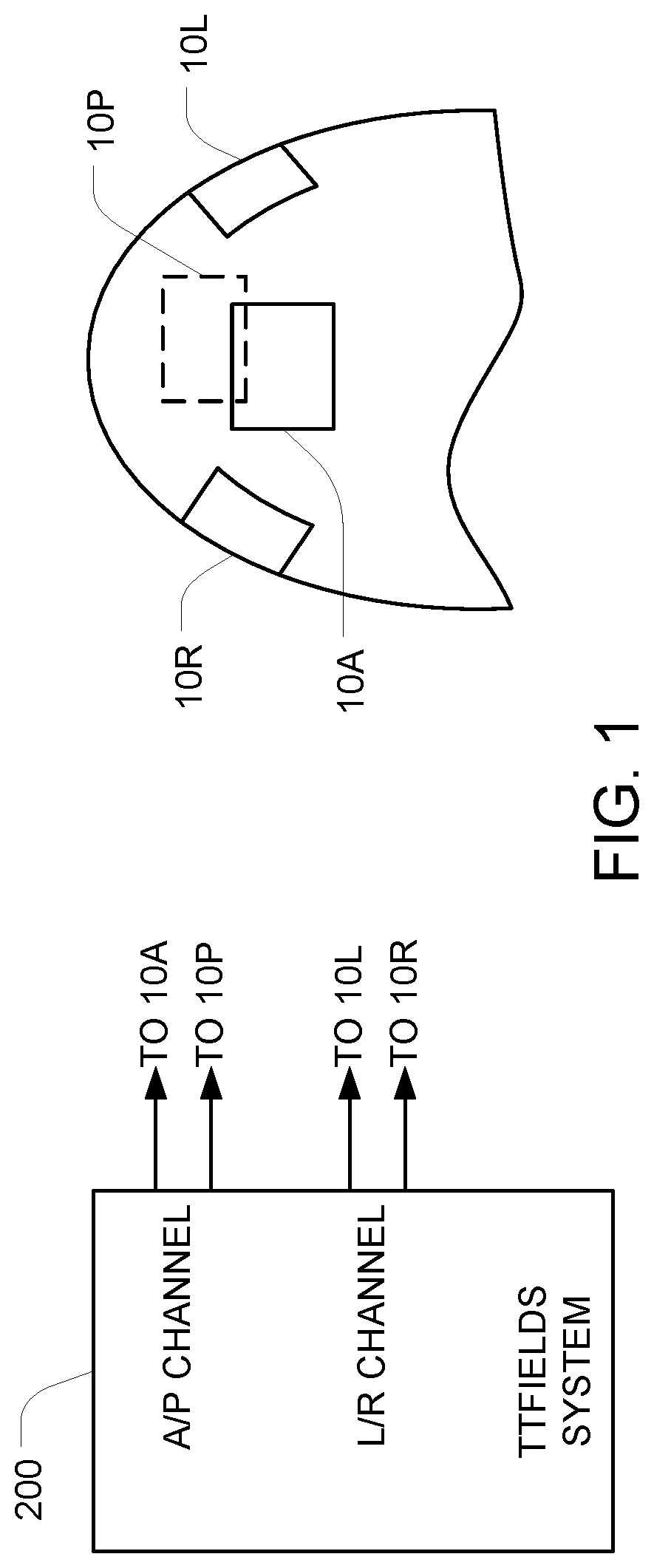
[0037]FIG. 1 is a system block diagram of an embodiment in which a TTFields system 200 drives a set of TTFields transducer arrays 10L, 10R, 10A, and 10P with AC signals at a frequency between 50 and 500 kHz or between 50 kHz and 1 MHz. One pair of transducer arrays (10L / 10R) is positioned to the left and right of the tumor, and the other pair of transducer arrays (10A / 10P) is positioned anterior and posterior to the tumor.

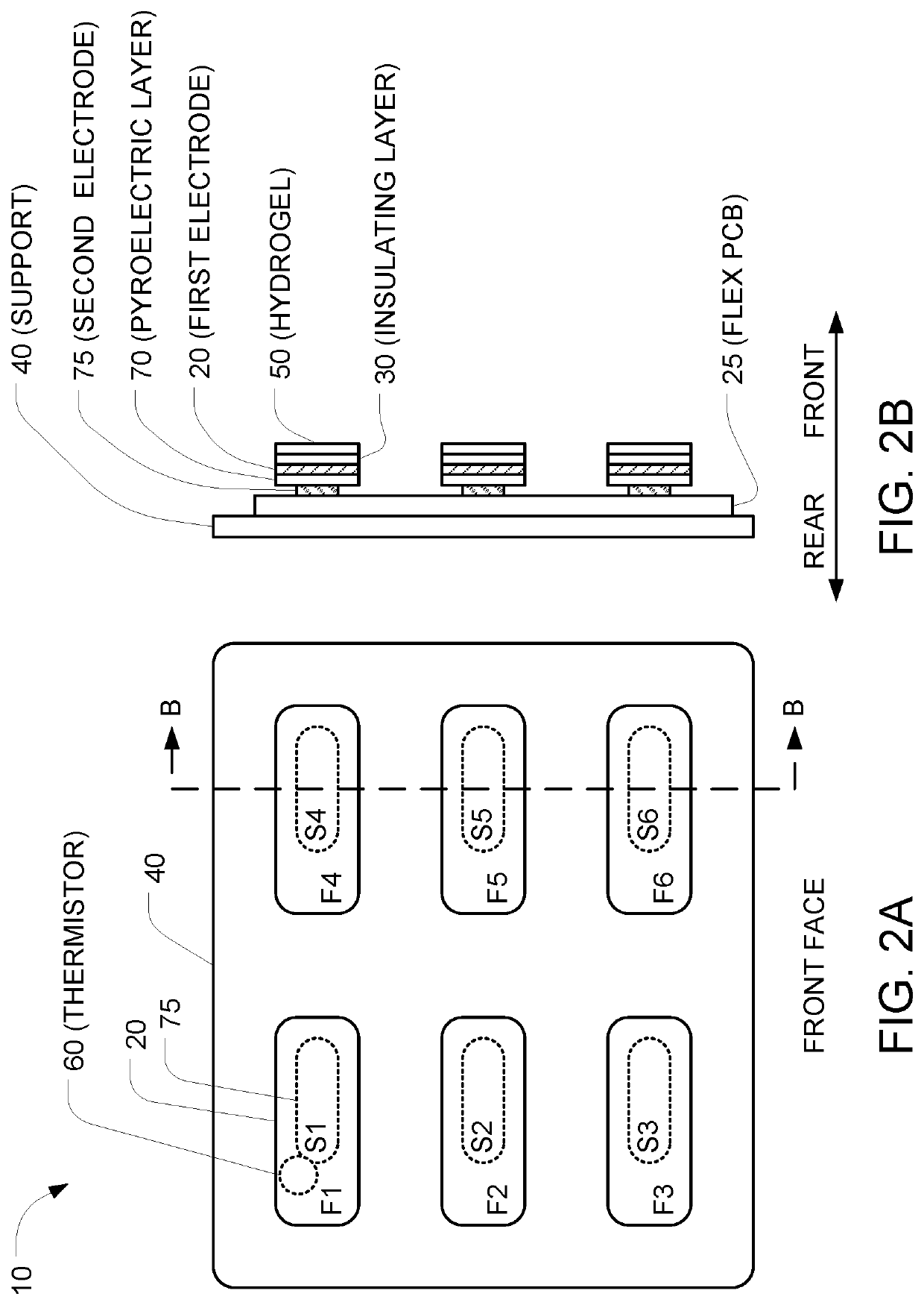
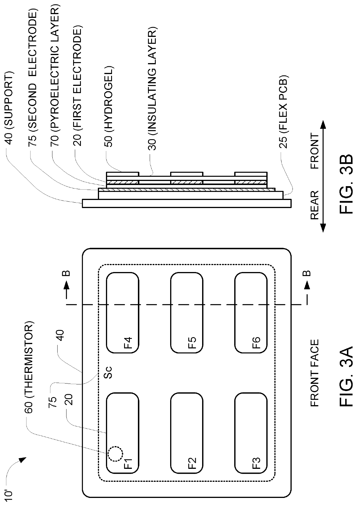
[0038]As described below in connection with FIGS. 2-3, each of the transducer arrays includes a plurality of individual electrode elements. And as described below in connection with FIG. 4, the TTFields system 200 (a) applies an AC voltage between selected electrode elements within the left transducer array 10L and selected elements within the right transducer array 10R for an interval of time (e.g., one second); then (b) applies an AC voltage between selected electrode elements within the anterior transducer array 10A and selected elements within the posterior tra...


PUM

PropertyMeasurementUnit
dielectric constantaaaaaaaaaa
temperaturesaaaaaaaaaa
frequencyaaaaaaaaaa

Abstract

TTFields are applied using transducer arrays made from a plurality of individual electrode elements. The temperatures of those electrode elements can be normalized by positioning respective regions of pyroelectric material in thermal contact with the electrode elements, and subsequently applying an AC signal to each of the electrode elements at respective duty cycles so that an alternating electric field is induced within the subject. For each of the regions of the pyroelectric material, an electrical characteristic that is related to temperature is measured after the AC signal turns off. The duty cycles of the AC signals that are applied to the electrode elements is adjusted until the measured electrical characteristics indicate that the temperatures of all the regions of the pyroelectric material have equalized to within 1° C.

Description

CROSS REFERENCE TO RELATED APPLICATIONS[0001]This Application claims the benefit of U.S. Provisional Application 63 / 126,911, filed Dec. 17, 2020, which is incorporated herein by reference in its entirety.BACKGROUND[0002]Tumor Treating Fields, or TTFields, are alternating electric fields within the intermediate frequency range (e.g., 100-500 kHz) that inhibit cancer cell growth. This non-invasive treatment targets solid tumors and is described in U.S. Pat. No. 7,565,205, which is incorporated herein by reference in its entirety. 200 kHz TTFields are FDA approved for the treatment of glioblastoma (GBM), and may be delivered, for example, via the prior art Optune™ system. Optune™ includes an electric field generator and two pairs of transducer arrays (i.e., electrode arrays) that are placed on the patient's shaved head. One pair of arrays (L / R) is positioned to the left and right of the tumor, and the other pair of arrays (A / P) is positioned anterior and posterior to the tumor. The Opt...

Claims


Application Information

Patent Timeline
Patent Type & Authority Applications(United States)
IPC IPC(8): A61N1/40H01L37/02
CPCA61N1/40H01L37/02A61N1/0476A61N1/36002A61N1/3603A61N1/0456A61N1/0529A61N1/36025H10N15/10
Inventor WASSERMAN, YORAMOBUCHOVSKY, STASKUPLENNIK, NATALIYA
Owner NOVOCURE GMBH
Why Eureka
Try Eureka