Cooling structure for electric vehicle

a technology for electric vehicles and cooling structures, applied in the direction of structure associations, cycle equipments, optical signals, etc., can solve the problems of increasing the electrical resistance of the windings, lowering efficiency, and increasing the temperature of the coils, so as to achieve simple structure, increase the effect of size, weight, cos

Active Publication Date: 2015-10-13
KAWASAKI MOTORS LTD
View PDF20 Cites 28 Cited by
  • Summary
  • Abstract
  • Description
  • Claims
  • Application Information

AI Technical Summary

Benefits of technology

[0029]According to the cooling structure for an electric vehicle according to the present invention, the coolant is directly applied to the traveling electric motor and power supply circuit which are easy to rise to a high temperature. And the coolant which has deprived the traveling electric motor and power supply circuit of heat is circulated between the cooling site and the heat exchanger so that the coolant will heat-exchange with the traveling wind. For this reason, as high cooling effect as possible may be expected, the structure is simple, and increases in size, weight, cost, etc are scarcely anticipated.

Problems solved by technology

A leading cause of the heat is generation of heat from a coil attributable to resistance of electrical currents flowing in windings (so-called copper loss).
This causes a rise in the temperature of the coil, increasing the electrical resistance of the windings and lowering efficiency.
The increased electrical resistance leads to generation of the heat again, falling in a vicious cycle of the generation of heat, the rise in temperature, and the increase in electrical resistance.
This becomes an obstacle to improving output of a motor.
In addition, the generation of heat from an inverter (power supply circuit) for supplying electric power to an electric motor has also been a problem.

Method used


Image

  • Cooling structure for electric vehicle
  • Cooling structure for electric vehicle
  • Cooling structure for electric vehicle

Examples


first embodiment

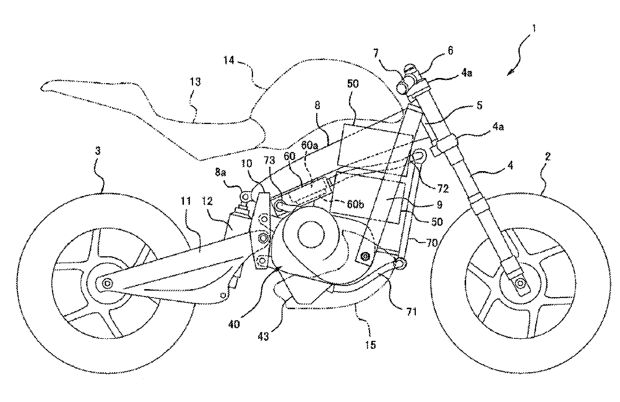
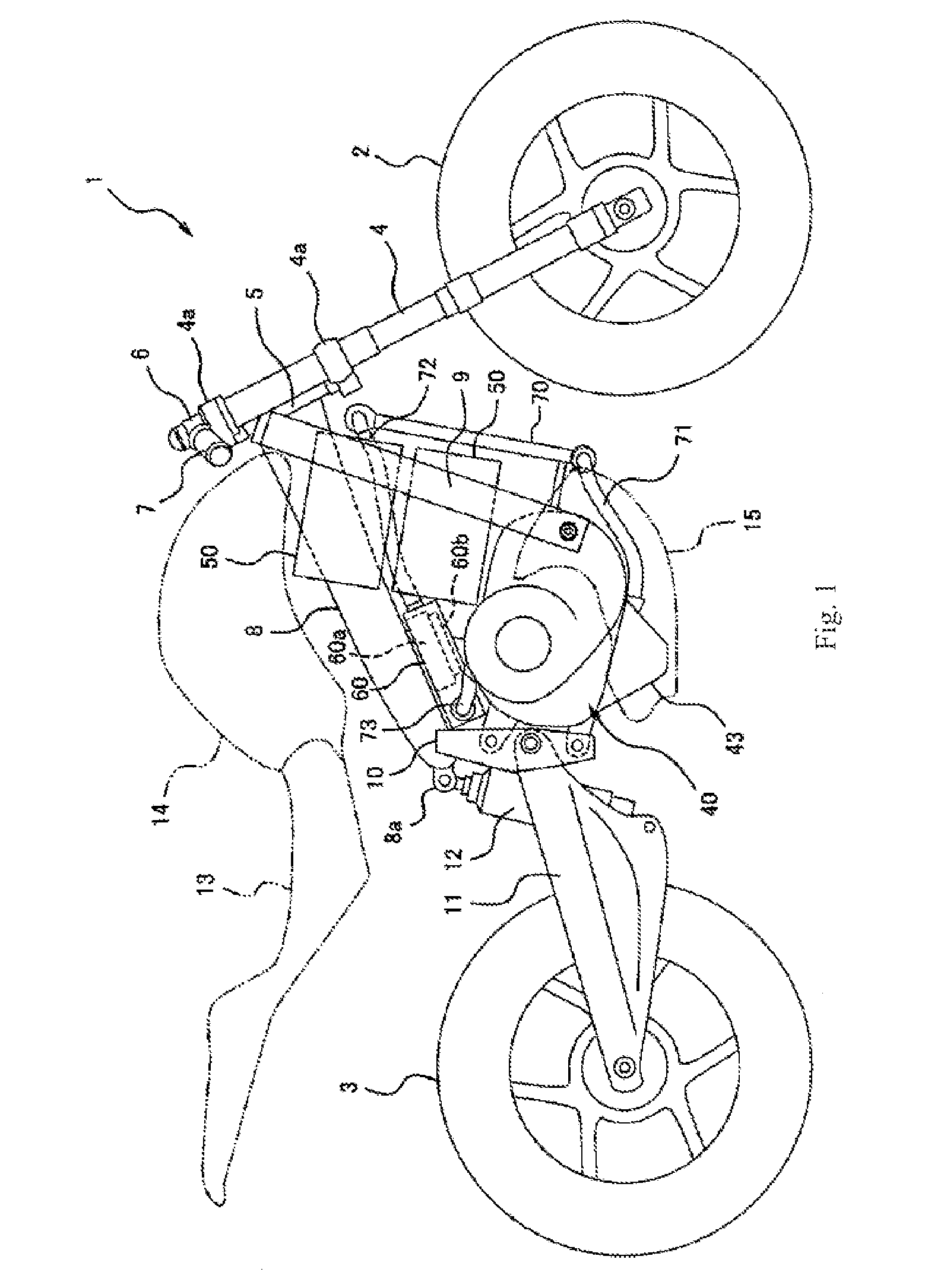
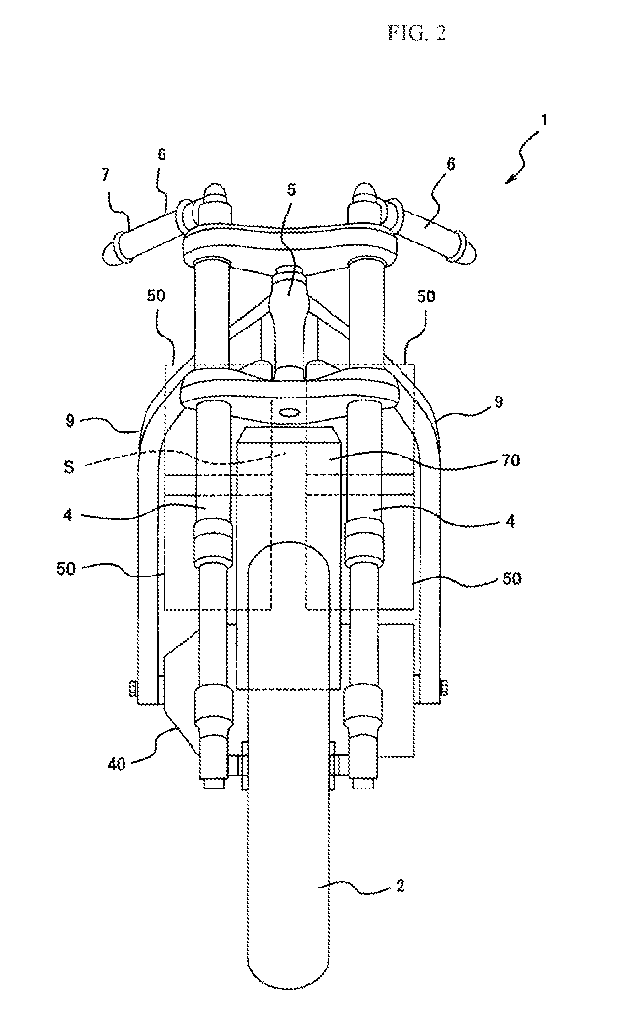
[0041]FIG. 1 is a right side view illustrating the main parts, such as a body frame, a power plant, and wheels, of an electric motorcycle 1 (electric vehicle) according to a first embodiment of the present invention, and FIG. 2 is a front view illustrating the same viewed from the front. As illustrated in FIG. 1, the electric motorcycle 1 includes a front wheel 2 as a steering wheel and a rear wheel 3 as a driving wheel. The front wheel 2 is freely rotatably supported by lower end portions of a pair of left and right front forks 4 which almost vertically extend. On the other hand, upper portions of the front forks 4 are supported by a steering shaft (not illustrated) via a pair of upper and lower brackets 4a.

[0042]The steering shaft is freely rotatably supported by a head pipe 5 in a state of being inserted in the head pipe 5 of the body side, and constitutes a steering shaft. A bar-type handle 6, which extends rightward and leftward like a bar, is attached to the upper bracket 4a,...

second embodiment

[0079]FIGS. 6 and 7 illustrate an electric motorcycle 101 according to a second embodiment of the present invention. Both figures correspond to FIGS. 1 and 3 of the first embodiment, respectively. The electric motorcycle 101 of the second embodiment mainly differs in the structure of a power plant from the first embodiment and hence differs also in mounting positions of batteries 50 and a power control controller 60, but it does not differ in the other basic structure. Accordingly, corresponding members are denoted by the same reference signs throughout all the drawings, and a repetitive description will be avoided.

[0080]A power plant 80 of the second embodiment does not include a transmission device 30 so that the power plant 80 is very compact in a forward and rearward direction as illustrated in FIG. 6. For this reason, as illustrated in the drawing, down frames 9 extend rearward from a lower end, and a case of the power plant 80 is fastened to rear ends of the down frames 9. In ...


PUM


Abstract

Provided is an electric motorcycle including a traveling motor, and a power supply circuit of an inverter and the like, in which a non-conducting cooling oil is supplied to be brought into direct contact with at least one of an electromagnetic coil of the traveling motor and a circuit board of the inverter. A radiator is disposed outside cases of a power plant and a power control controller so as to allow a traveling wind to pass by. Cooling oil is circulated between the radiator and a case of at least one of the power plant and power control controller. A cooling structure for an electric motor and the like that can obtain a higher cooling efficiency than a conventional art while having a simple structure which hardly causes increases in size, weight, cost, and the like can be provided.

Description

TECHNICAL FIELD[0001]The present invention relates to a cooling structure for a motor and a power supply circuit in an electric vehicle such as an electric car, an electric motorcycle, or a hybrid car.BACKGROUND ART[0002]In recent years, from the prospect of depletion of oil resources in the future with a growing interest in the environment, it is more highly demanded than before to reduce fuel consumption in an automobile and a motorcycle, etc. On the other hand, there has been fast progress in the research and development of secondary cells represented by a lithium ion cell, and attempts to use electricity as a power source for driving the electric car or hybrid become popular.[0003]Generally an electric motor has quite high energy efficiency compared with an internal-combustion engine, but it generates heat during its operation. A leading cause of the heat is generation of heat from a coil attributable to resistance of electrical currents flowing in windings (so-called copper los...

Claims


Application Information

Patent Timeline
Patent Type & Authority Patents(United States)
IPC IPC(8): H02K9/00B60K1/02B60K1/04B60K11/02B60L15/20B62K11/04H02K7/116H02K11/04B60L1/00B60L3/00B60L7/14B60L11/18B60K1/00H02K9/19B60K11/04B62J11/19
CPCH02K9/19B60K1/02B60K1/04B60K11/02B60K11/04B60L1/003B60L3/003B60L3/0061B60L7/14B60L11/1803B60L11/1864B60L11/1874B60L11/1877B60L15/2009B60L15/2054B62K11/04H02K7/116H02K11/048B60K1/00Y02T10/641B60K2001/006B60L2200/12B60L2220/50B60L2240/12B60L2240/36B60L2240/421B60L2240/425B60L2240/486B60L2240/525B60L2240/545B60Y2200/12B62K2204/00B62K2208/00Y02T10/72B60L50/51B60L58/21B60L58/26B60L50/66Y02T10/64Y02T10/70B62J43/28B62J43/16H02K11/05
Inventor MATSUDA, YOSHIMOTO
Owner KAWASAKI MOTORS LTD
Why Eureka
Try Eureka