UAV having configurable fuel cell power system

Pending Publication Date: 2022-06-23
INTELLIGENT ENERGY LTD
View PDF0 Cites 0 Cited by
  • Summary
  • Abstract
  • Description
  • Claims
  • Application Information

AI Technical Summary

Benefits of technology

[0050]In UAV implementations where two or more modules 50 are arranged in parallel, the power doubling may be based on an output voltage of each of the two or more modules 50 being the same as if each stack was operating independently and on an output current from the two or more modules 50 being doubled. In UAV implementations where modules 50 are connected in parallel, a total output current greater than that available from one individual module 50 may be obtained. The parallel configuration of modules 50 within UAV 100 may also be beneficial by providing redundancy, enhancing reliability, avoiding PCB thermal issues and boosting system efficiency. In some exemplary implementations, power controller 40 may be configured to balance a current from each of modules 50. That is, some exemplary implementations of modules 50 in the parallel configuration may be performed such that the load current is shared, e.g., to prevent one of modules 50 from shutting down before the required current is delivered. Some exemplary implementations may actively balance the output current from modules 50 using a control loop to compensate betwe

Problems solved by technology

For many applications, the computing power required on-board the vehicle in order to provide necessary functionality may represent a significant power demand.
When power is supplied only by batteries, the flight time of UAVs may be limited because of the power demands of the propulsion and other on-board systems.
However, the power generating capacity of a photovoltaic panel depends on the ambient weather conditions and the time of day, and, subsequently, photovoltaic panels may not be appropriate for use in all circumstances.
In addition, the power generation capacity of photovoltaic panels may be inadequate for some applications in which either high power (speed) propulsion is required, or the on-board systems of the UAV that provide its functionality are particularly heavy or demand substantial electrical power.
Fuel cells ar

Method used


Image

  • UAV having configurable fuel cell power system
  • UAV having configurable fuel cell power system
  • UAV having configurable fuel cell power system

Examples


Example

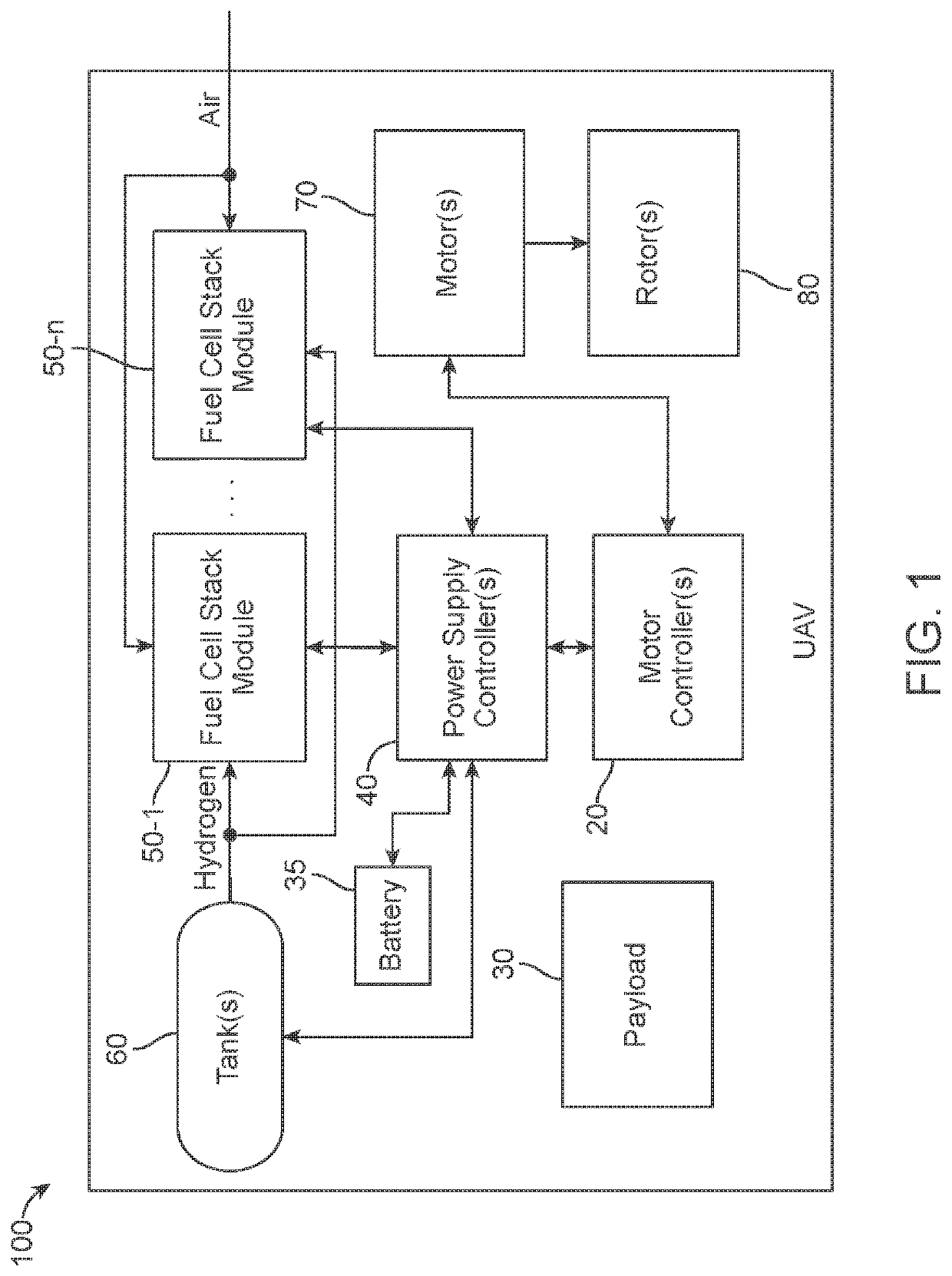
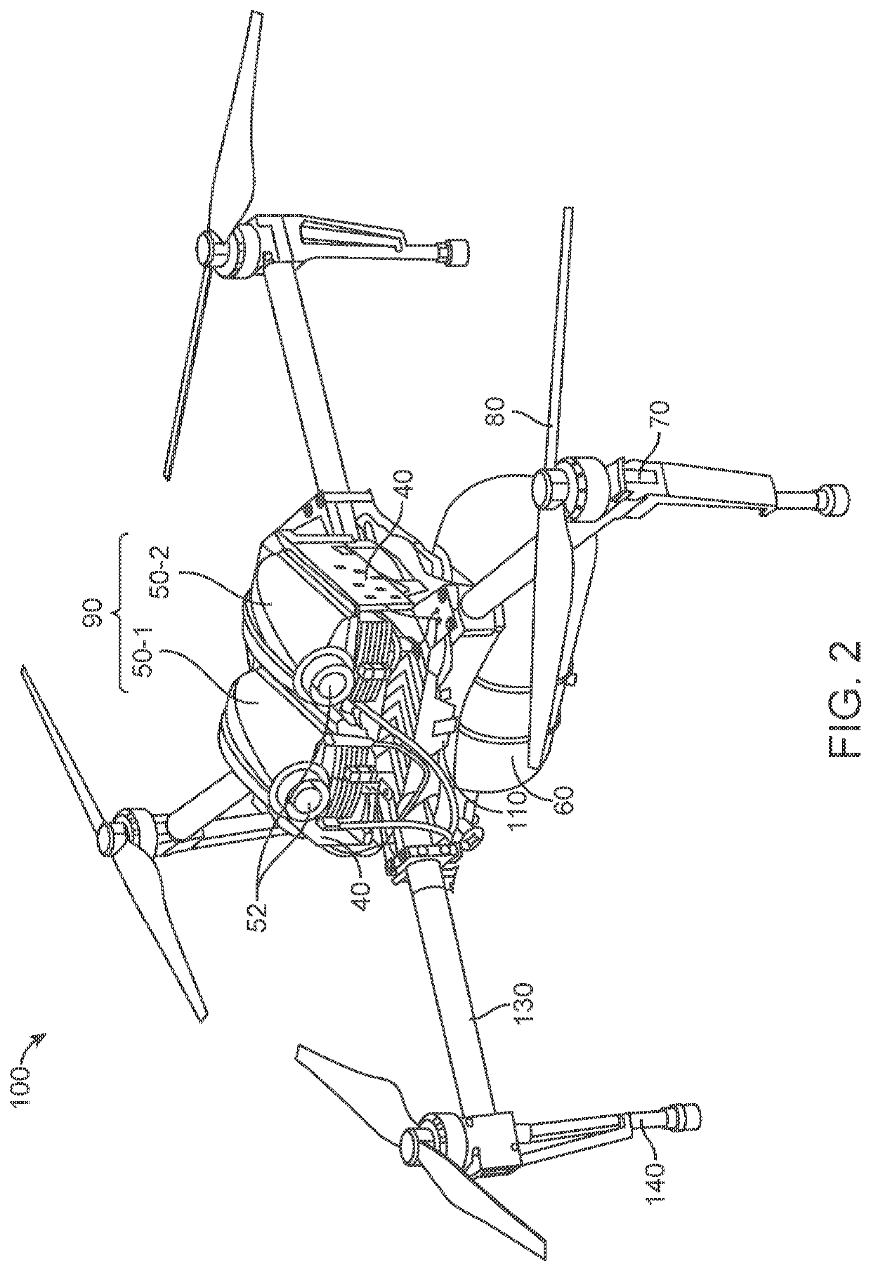
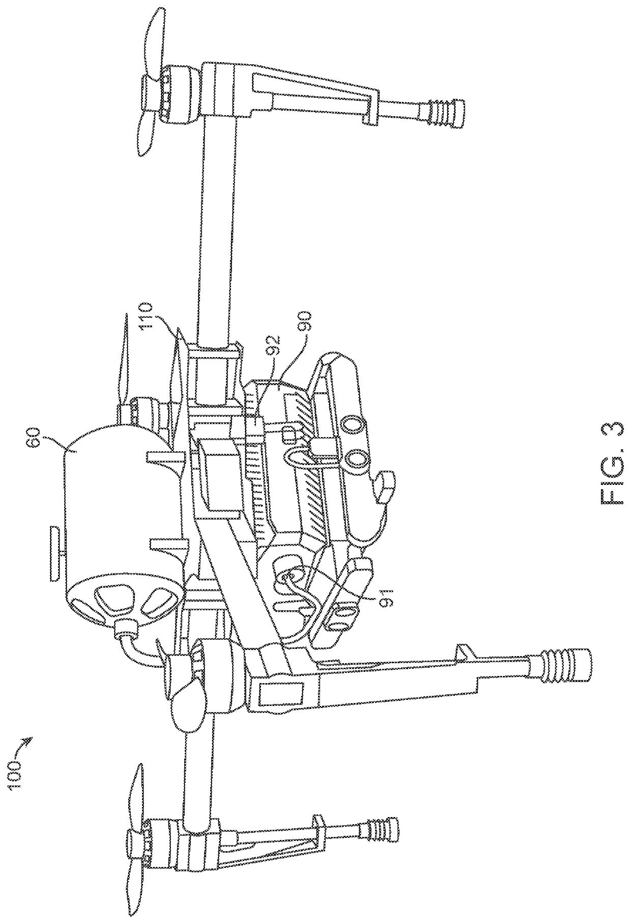
[0034]The components in the figures are not necessarily to scale, emphasis instead being placed upon illustrating the principles of the disclosure. All reference numerals, designators and callouts in the figures and Appendices are hereby incorporated by this reference as if fully set forth herein. The failure to number an element in a figure is not intended to waive any rights. Unnumbered references may also be identified by alpha characters in the figures.

[0035]Further Disclosure

[0036]The following detailed description includes references to the accompanying drawings, which form a part of the detailed description. The drawings show, by way of illustration, specific embodiments in which some disclosed aspects may be practiced. These embodiments, which are also referred to herein as “examples” or “options,” are described in enough detail to enable those skilled in the art to practice methods and devices disclosed. The embodiments may be combined, other embodiments may be utilized, or...


PUM


Abstract

The present disclosure pertains to an unmanned aerial vehicle system. Some exemplary implementations may include: a mounting frame (110) onto which at least a payload (30) is affixed; a plurality of fuel cell stacks (50) operable in a predefined configuration, each of the plurality of stacks (50) being in a separate package; one or more tanks (60) configured to supply hydrogen tot the plurality of stacks; a propulsion system (70, 80) configured to receive an out put power generated from the plurality of stacks (50); and a power controller (40) configured to couple the plurality of stacks in the predefined configuration.

Description

[0001]This application is the US National Phase of International application No. PCT / GB2020 / 051006, filed Apr. 23, 2020, titled UAV HAVING CONFIGURABLE FUEL CELL POWER SYSTEM, which claims the benefit of Great Britain 1905672.0, filed Apr. 23, 2019, the contents of which are incorporated by reference herein in their entirety.TECHNICAL FIELD[0002]The present disclosure relates generally to configurable systems for assembling fuel cell power modules (FCPMs) for an unmanned aerial vehicle (UAV). Further disclosed is a way to gain center of gravity (CoG) flexibility and control, when integrating fuel cell stacks onto a UAV.BACKGROUND[0003]UAVs, which are also known as drones, are becoming increasingly popular for applications such as photography, surveillance, farm maintenance (e.g., pest control), atmospheric research, fire control, wildlife monitoring, package delivery, and military purposes. UAVs generally fall into two categories, namely multirotor UAVs used generally in commercial ...

Claims


Application Information

Patent Timeline
IPC IPC(8): B64C39/02H01M8/249H01M8/04537H01M8/04858
CPCB64C39/024H01M8/249B64D2041/005H01M8/0494H01M8/04619B64C17/00B64D27/24B64D37/04B64D37/30B64D2221/00Y02T50/60Y02E60/10H01M8/04679H01M2250/20H01M8/04201B64U50/19Y02T90/40H01M8/00Y02E60/50H01M2220/20B64U10/10B64U30/20B64U50/32
Inventor KELLY, ANDREW PAULSCRACE, MATHEW CHARLESWILDE, RONAN ELLIOTLAWSON, GEOFF MARKFRASER, IAIN MATHESON
Owner INTELLIGENT ENERGY LTD
Why Eureka
Try Eureka