Display device, method of driving display device, and electronic apparatus

a display device and display device technology, applied in the direction of electrical devices, semiconductor devices, instruments, etc., can solve the problem that the current modulation scheme in which a current value flowing through an element is controlled is considered unsuitable for driving the light-emitting diodes

Active Publication Date: 2022-06-30
SONY CORP
View PDF12 Cites 1 Cited by
  • Summary
  • Abstract
  • Description
  • Claims
  • Application Information

AI Technical Summary

Benefits of technology

[0009]Therefore, the present disclosure aims to provide a display device that is resistant to noise, various types of fluctuations, and the like with a simple circuit configuration, and has high gray-scale performance and no chromaticity change without using as much as possible a low current range that has many issues specifically in driving a light-emitting diode, a method of driving a display device, and an electronic apparatus including the display device.Means for Solving the Problems

Problems solved by technology

Therefore, a current modulation scheme in which a current value flowing through an element is controlled was considered unsuitable for driving the light-emitting diode.

Method used


Image

  • Display device, method of driving display device, and electronic apparatus
  • Display device, method of driving display device, and electronic apparatus
  • Display device, method of driving display device, and electronic apparatus

Examples


example 1

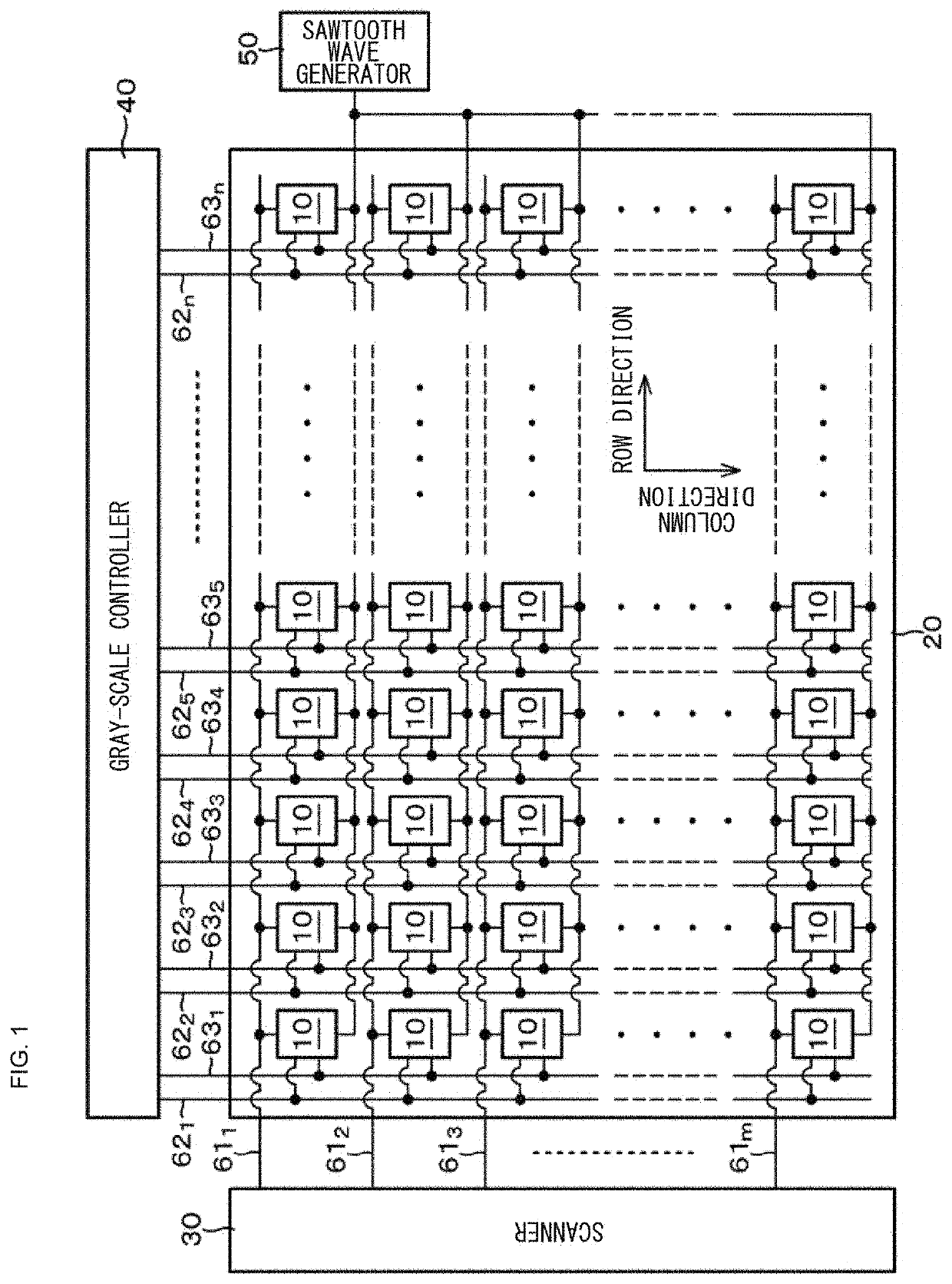
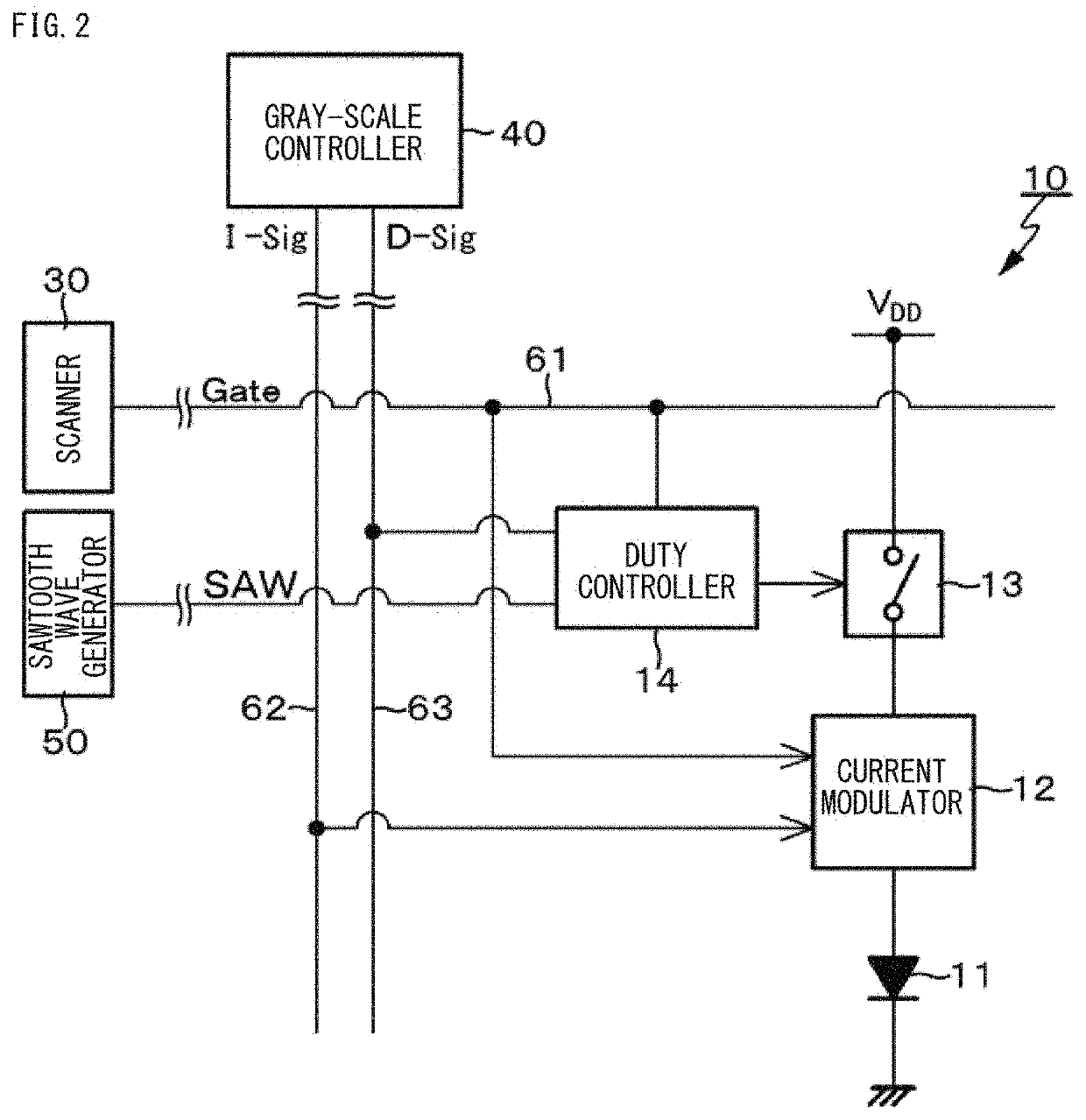
[0057]Example 1 is a circuit example of the pixel circuit 10 according to Example 1. FIG. 2 illustrates a circuit diagram of the circuit example of the pixel circuit 10 according to Example 1.

[0058]The pixel circuit 10 has a configuration including a light-emitting element 11, a current modulator 12, a switch element 13, and a duty controller 14. It is possible to use a self-emitting element such as a light-emitting diode (LED) or an organic EL element as the light-emitting element 11.

[0059]In the pixel circuit 10 according to Example 1, a light-emitting diode (LED) is used as the light-emitting element 11. It is to be noted that it is known that in the light-emitting diode, a spectrum exhibits a so-called blue shift in which the spectrum is shifted to blue side by a current (a light emission current) flowing through the element, thereby causing fluctuations in chromaticity by the value of the light emission current and large luminance variation in a low current range.

[0060]The curr...

example 2

[0066]Example 2 is an example of a driving method in which gray-scale control is performed with use of the pixel circuit 10 according to Example 1. The gray-scale control is performed in the pixel circuit 10 according to Example 1 under control by the gray-scale controller 40 by control of the current value of the light-emitting element 11 by the current modulator 12 and on / off control of the switch element 13 by the duty controller 14.

[0067]Gray-scale change is considered, for example, in a case where the pixel circuit 10 according to Example 1 is used to decrease luminance from a state of a maximum light emission current value at a maximum light emission duty.

[0068]First, the current value of light-emitting element 11 is decreased finely, and the current value is decreased until luminance reaches a certain ratio (proportion) to maximum luminance. Then, the light emission duty is decreased to the ratio at this time, and the current value of the light-emitting element 11 is returned...

example 3

[0075]Example 3 is an example of a driving method in which chromaticity correction is performed in a current range used for gray-scale control.

[0076]As described above, according to the driving method according to Example 2, it is possible to implement gray-scale control using only a limited current range (the current range X illustrated in FIG. 5). However, in the light-emitting element 11, specifically, the light-emitting diode, a spectrum exhibits a blue shift by the light emission current as described above, thereby causing chromaticity change by the current value of the light emission current. FIG. 8 illustrates a luminance-chromaticity difference characteristic diagram in a case where chromaticity is not corrected. In displaying or the like of an image of which colors change smoothly, chromaticity change by the light emission current may cause an issue such as banding (dark and light stripes).

[0077]In the driving method according to Example 3, chromaticity correction in a sing...


PUM


Abstract

A display device of the present disclosure is provided with a pixel circuit that includes a light-emitting element; a current modulator that controls a current value flowing through the light-emitting element; a current breaker that interrupts a current flowing through the light-emitting element; and a gray-scale controller that controls the current modulator and the current breaker to perform gray-scale control. The gray-scale controller discretely controls a light emission duty of the light-emitting element through the current breaker, and controls, through the current modulator, the current value flowing through the light-emitting element in accordance with the light emission duty of the light-emitting element.

Description

TECHNICAL FIELD[0001]The present disclosure relates to a display device, a method of driving a display device, and an electronic apparatus.BACKGROUND ART[0002]As a light-emitting element (specifically, a self-emitting element) of a display device, it is possible to exemplify a light-emitting diode (LED), an organic EL (electroluminescence) element, and the like. Of these self-emitting elements, the light-emitting diode has attracted attention as a light-emitting element for a next-generation display because of less degradation in the element, high efficiency, and the like.[0003]Incidentally, it is known that the light-emitting diode has a characteristic in which a spectrum is shifted to blue side by a current (a light emission current) flowing through the element, thereby causing fluctuations in chromaticity by the value of the light emission current, and large luminance variation in a low current range. Therefore, a current modulation scheme in which a current value flowing through...

Claims


Application Information

Patent Timeline
Patent Type & Authority Applications(United States)
IPC IPC(8): G09G3/20G09G3/3233
CPCG09G3/2007G09G3/3233G09G2310/0243G09G2310/06G09G2320/0242H01L33/00G09G2310/066G09G2300/0852G09G2310/0262G09G3/2014H10K59/00H10K50/00G09G3/32G09G5/02G09G2320/0271G09G3/3208G09G3/3225
Inventor KIKUCHI, KENSUGIYAMA, TAKAAKI
Owner SONY CORP
Why Eureka
Try Eureka