Installation structure for solar cell module, and installation method for solar cell module

a solar cell module and installation structure technology, applied in electrical equipment, covering/lining, construction, etc., can solve the problems of complicated cable connection work and difficult to say that the safety is high

Pending Publication Date: 2022-06-30
KANEKA CORP
View PDF0 Cites 0 Cited by
  • Summary
  • Abstract
  • Description
  • Claims
  • Application Information

AI Technical Summary

Problems solved by technology

With the solar cell module installation structures described in Japanese Patent No. 5778090, Japanese Patent No. 6190613 and Japanese Patent No. 6433058, a worker goes behind a solar cell module in a state where a large solar cell module is made to be slanted from a wall surface in order to perform cable connection work, and, in addition to the cable connection work being complicated, it is difficult to say that safety is high.

Method used


Image

  • Installation structure for solar cell module, and installation method for solar cell module
  • Installation structure for solar cell module, and installation method for solar cell module
  • Installation structure for solar cell module, and installation method for solar cell module

Examples


Embodiment Construction

[0027]With reference to the attached drawings, description is given below regarding an example of an embodiment of the present disclosure. Note that the same reference symbol is applied to the same or corresponding portions in the drawings. For convenience, there are cases where hatching, member symbols, etc. are omitted, but in these cases other drawings are to be referred to.

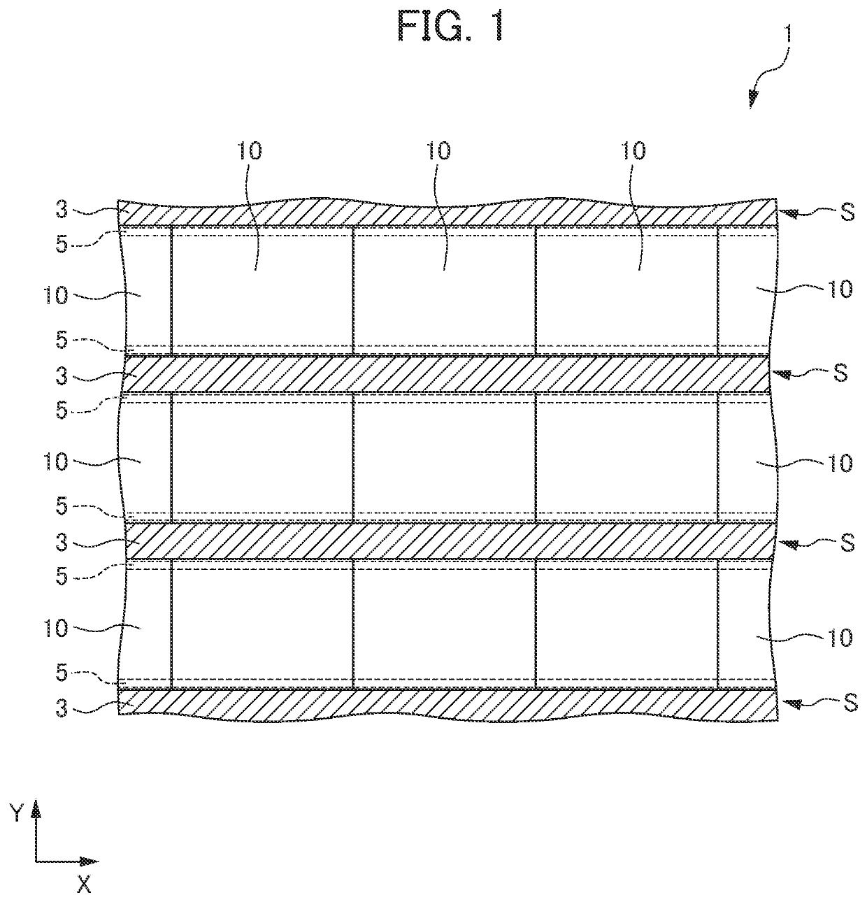
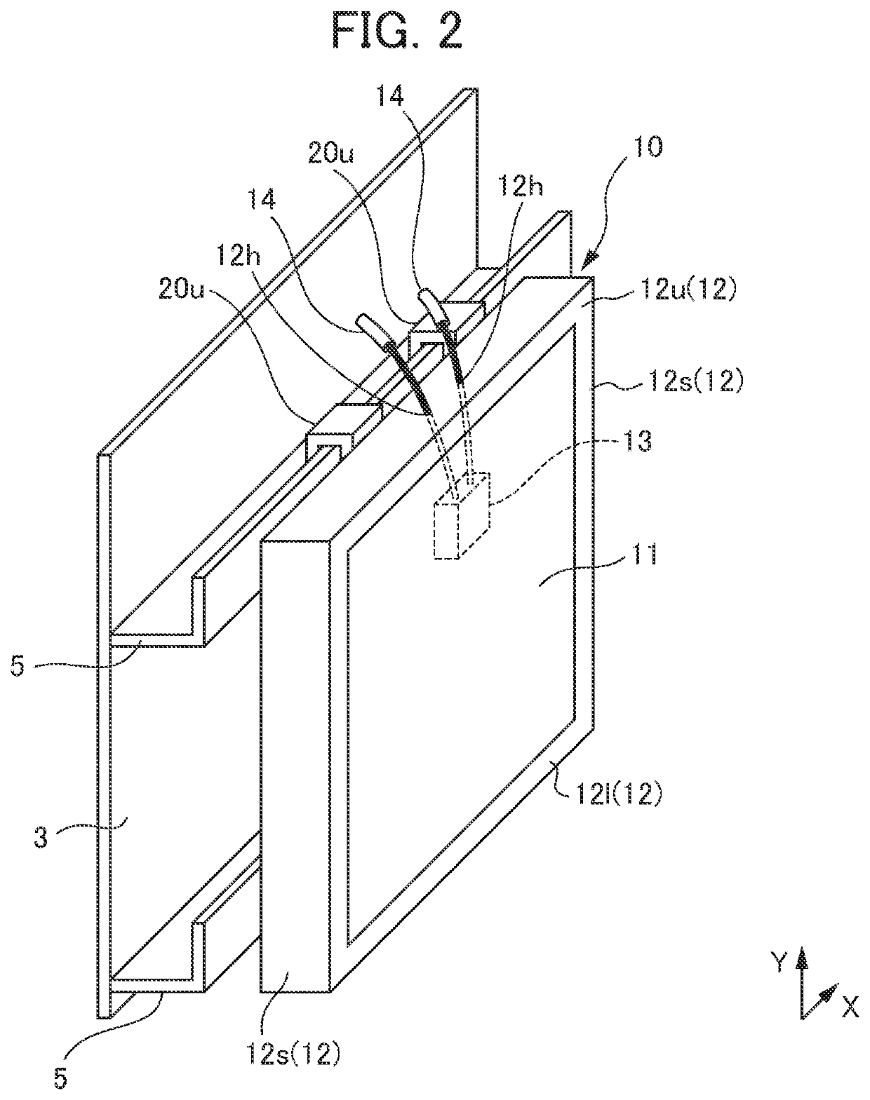
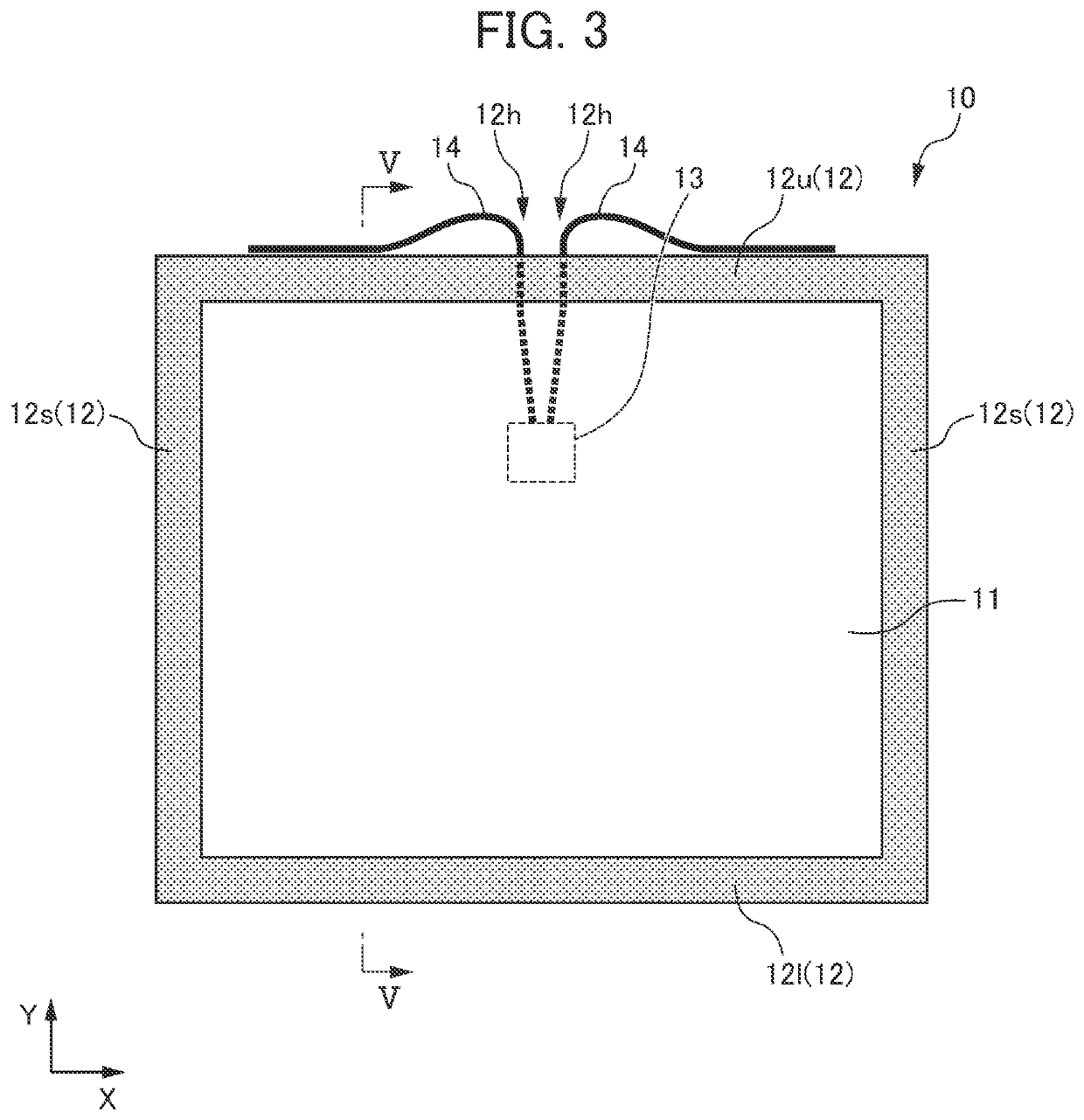
[0028]FIG. 1 is a view illustrating a solar cell module installation structure according to the present embodiment. FIG. 2 is a perspective view illustrating, in an enlarged manner, a portion of the solar cell module installation structure illustrated in FIG. 1. FIG. 3 is a view of the enlarged portion of the solar cell module installation structure illustrated in FIG. 2, seen from in front. FIG. 4 is a view of the enlarged portion of the solar cell module installation structure illustrated in FIG. 3, seen from above. FIG. 5 is a V-V line cross section of the enlarged portion of the solar cell module installat...


PUM


Abstract

An installation structure for a solar cell module comprises engagement parts attached to a wall surface; and a plurality of solar cell modules which are installed on the wall surface by engaging with the engagement parts. An upper frame part of the solar cell module has an engaging part for engaging with the engagement parts, and the upper frame part has a hole for letting out a cable from the solar cell module to outside. For vertically adjacent solar cell modules, a space for connecting and installing the cable let out to the outside is present between the upper frame part of the lower solar cell module and a lower frame part of the upper solar cell module.

Description

CROSS-REFERENCE TO RELATED APPLICATIONS[0001]This application claims benefit of priority to International Patent Application No. PCT / JP2020 / 031981, filed Aug. 25, 2020, and to Japanese Patent Application No. 2019-169748, filed Sep. 18, 2019, the entire contents of each are incorporated herein by reference.BACKGROUNDTechnical Field:[0002]The present disclosure relates to a solar cell module installation structure, and a solar cell module installation method.Background Art:[0003]A structure in which solar cell modules are installed with a two-dimensional shape on a wall surface of a construction such as a building is known, as described, for example, in Japanese Patent No. 5778090, Japanese Patent No. 6190613 and Japanese Patent No. 6433058. With the solar cell module installation structures described in Japanese Patent No. 5778090, Japanese Patent No. 6190613 and Japanese Patent No. 6433058, an upper frame of a solar cell module is hung on a wall surface of a construction, and the so...

Claims


Application Information

Patent Timeline
Patent Type & Authority Applications(United States)
IPC IPC(8): H02S20/26H02S30/10H02S40/34E04F13/08
CPCH02S20/26E04F13/081H02S40/34H02S30/10H02S40/36H02S20/22E04F13/083
Inventor SAWADA, TORU
Owner KANEKA CORP
Why Eureka
Try Eureka