Acoustic wave filter

Pending Publication Date: 2022-07-07
MURATA MFG CO LTD
View PDF0 Cites 0 Cited by
  • Summary
  • Abstract
  • Description
  • Claims
  • Application Information

AI Technical Summary

Benefits of technology

[0010]According to preferred embodiments of the present invention, acoustic wave filters can be provided that are each able to red

Problems solved by technology

However, when the structure in which the first and second edge regions are the widened portions is used in each of the acoustic wave resonators of the acoustic wave filter and particularly when a reduction in size of the acoustic wave filter is attempted, ripples due to a transverse mode cannot be sufficiently suppressed in som

Method used


Image

  • Acoustic wave filter
  • Acoustic wave filter
  • Acoustic wave filter

Examples


Example

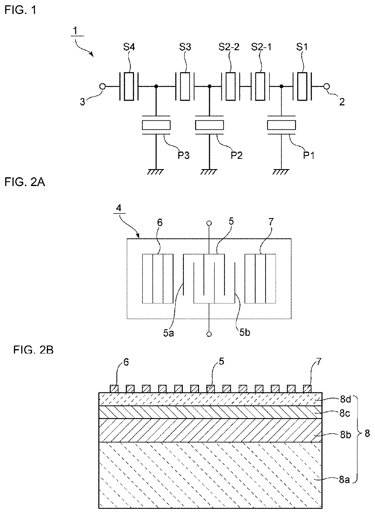
[0062]Acoustic wave filters of Example 1 of the acoustic wave filter 1 illustrated in FIG. 1 and Comparative Example 1 for comparison were prepared. A configuration of the piezoelectric substrate 8 in Example 1 was the same as or similar to the first and second acoustic wave resonators described above. In Example 1, an acoustic wave filter for Band25Tx was provided. A center frequency is about 1822.5 MHz. Design parameters of the series arm resonators S1, S2-1, S2-2, S3, and S4 and the parallel arm resonators P1 to P3 were set as shown in Table 1 below.

TABLE 1S4P3S3P2S2-2S2-1P1S1Number of Pairs ofPairs144180.5163.5131120120119.5130Electrode Fingers ofIDT ElectrodeNumber of ElectrodeNumber2121212121212121Fingers of ReflectorInterdigitation Widthμm24.330.236.451.424.124.157.334.9Duty0.50.50.50.50.50.50.50.5Wavelengthμm2.0132.1162.0302.0902.0012.0012.0882.005

[0063]In the acoustic wave filter of Example 1, the series arm resonator S3 is the first acoustic wave resonator, and the rest of...

Example

[0065]As Comparative Example 1, the acoustic wave filter of Comparative Example 1 was prepared similarly to Example 1, except that the series arm resonator S3 was also the second acoustic wave resonator.

[0066]In FIG. 6, a solid line indicates attenuation-frequency characteristics of the acoustic wave filter of Example 1, and a broken line indicates attenuation-frequency characteristics of the acoustic wave filter of the Comparative Example 1. Further, FIG. 7 is an enlarged portion showing a portion indicated with a scale of the attenuation on the left side of a portion indicated by the arrow B in FIG. 6.

[0067]As is clear from FIG. 6 and FIG. 7, according to the acoustic wave filter of Example 1, steepness of filter characteristics on a high-frequency side of a pass band is increased compared to the acoustic wave filter of Comparative Example 1. To be more specific, steepness from about 3 dB to about dB, which is a frequency range in which the attenuation increases from about 3 dB to...

Example

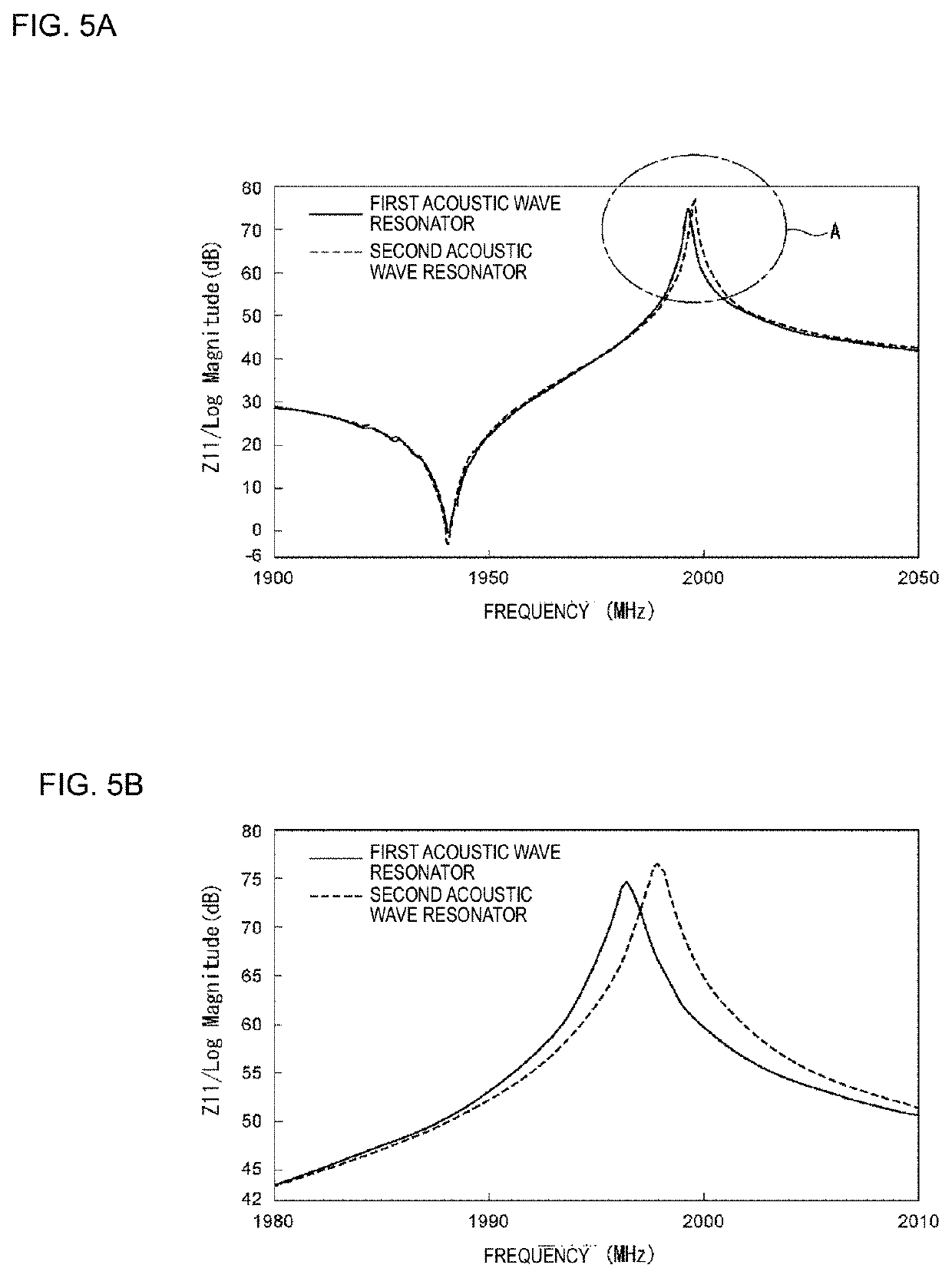
[0069]As Example 2 of a preferred embodiment of the present invention, a ladder filter of Example 2 was prepared similarly to the ladder filter of Comparative Example 1, except that only the parallel arm resonator P1 was a first acoustic wave resonator. The parallel arm resonator P1 of the ladder filter of Example 2 is defined by the first acoustic wave resonator as described above, and the configuration of the first acoustic wave resonator was similar to that of the first acoustic wave resonator illustrated in FIGS. 5A and 5B described above.

[0070]FIG. 8 is a diagram showing attenuation-frequency characteristics of the respective acoustic wave filters of Example 2 and Comparative Example 1. FIG. 9 is an enlarged diagram showing a portion indicated with a scale of the attenuation on the left side of a portion indicated by the arrow C in FIG. 8. A solid line indicates the characteristics of Example 2, and a broken line indicates the characteristics of Comparative Example 1.

[0071]As i...


PUM


Abstract

An acoustic wave filter includes acoustic wave resonators including a piezoelectric substrate and an IDT electrode including first and second electrode fingers. An intersecting region of the first and second electrode fingers includes a central region and first and second edge regions on outer side portions of the central region. An acoustic velocity in the first and second edge regions is lower than that in the central region, and the acoustic wave resonators include a first acoustic wave resonator with a width in the first and second edge regions larger than a width in the central region, and a second acoustic wave resonator including at least one of an acoustic velocity reducing film and an acoustic velocity increasing film in the central region, such that an acoustic velocity in the first and second edge regions is lower than acoustic velocity in the center region.

Description

CROSS REFERENCE TO RELATED APPLICATIONS[0001]This application claims the benefit of priority to Japanese Patent Application No. 2019-176704 filed on Sep. 27, 2019 and is a Continuation application of PCT Application No. PCT / JP2020 / 035303 filed on Sep. 17, 2020. The entire contents of each application are hereby incorporated herein by reference.BACKGROUND OF THE INVENTION1. Field of the Invention[0002]The present invention relates to a band-pass acoustic wave filter including a plurality of acoustic wave resonators.2. Description of Related Art[0003]Various band-pass acoustic wave filters including a plurality of acoustic wave resonators have been proposed. For example, in a ladder filter described in Japanese Unexamined Patent Application Publication No. 2002-217680, a series arm resonator and a parallel arm resonator are configured with acoustic wave resonators.[0004]In addition, Japanese Unexamined Patent Application Publication No. 2014-131351 discloses a structure in which a pis...

Claims


Application Information

Patent Timeline
IPC IPC(8): H03H9/56H03H9/205H03H9/02
CPCH03H9/568H03H9/02228H03H9/205H03H9/145H03H9/64H03H9/6496H03H9/13H03H9/54H03H9/1457H03H9/02574H03H9/02881H03H9/14541
Inventor TANIGUCHI, YASUMASADAIMON, KATSUYA
Owner MURATA MFG CO LTD
Why Eureka
Try Eureka