Wireline Clean-Out Tool Having Improved Capacity

a technology of wireline and cleaning tool, which is applied in the direction of survey, borehole/well accessories, separation processes, etc., can solve the problems of difficult to collect large amounts of debris with electromechanical equipment, low torque of equipment, and volatile character of system

Pending Publication Date: 2022-07-14
ALTUS INTERVENTION TECH AS
View PDF10 Cites 0 Cited by
  • Summary
  • Abstract
  • Description
  • Claims
  • Application Information

AI Technical Summary

Problems solved by technology

These materials are collected in a similar manner in the collection chamber, but have a volatile character and will leak out of the system when the debris-collecting tool is pulled up from a horizontal to a vertical well section.
It is very challenging to collect large amounts of debris with electromechanical equipment.
Such equipment generally has limited torque, because of the fact these tools are supplied via a cable from the surface.
Expressed differently, the amount of electrical power that can be fed through the cable is limited and thereby the amount of available torque is limited.
A major disadvantage of coiled tubing technology is the size of the equipment that is needed.
This equipment is very large, heavy and very space demanding.
Particularly when carried out on an oilrig this forms a major challenge.
All other activities on the rig generally need to be adapted and it takes a lot of time to set up the equipment before it can be used.
Once these campaigns have been started it becomes very difficult for wireline technologies to compete with coiled tubing technology.
However, in case there are only a few wellbores having reduced production a coiled tubing operation would take way too much time (and therefore money) for it to be commercially attractive.
Waiting for more wellbores to be ready for clean-out after setting up the coiled tubing equipment would involve enormous losses as well.
Even though this downhole tool string provides a clever solution for rotating the operational tool at a lower rotational speed than the pump it still involves a very complex solution, wherein particularly the gear section is space demanding and thus “eats” from the debris-collecting capacity of the downhole tool.
Even though this debris removal apparatus is capable of collecting different types of debris, it still suffers from rapid clogging of the filter and is also difficult to empty once filled.

Method used


Image

  • Wireline Clean-Out Tool Having Improved Capacity
  • Wireline Clean-Out Tool Having Improved Capacity
  • Wireline Clean-Out Tool Having Improved Capacity

Examples


first embodiment

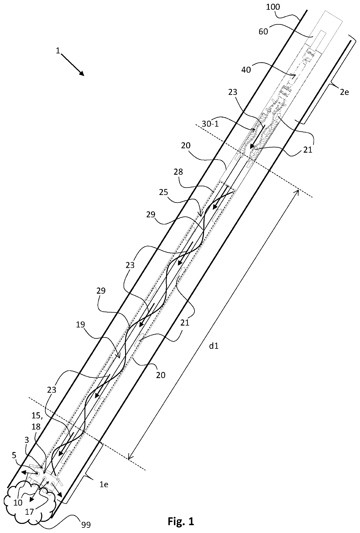
[0046]FIG. 1 shows a wireline clean-out tool 1 in accordance with the invention. The wireline clean-out tool is provided in a wellbore 100, which is clogged with debris 99 as illustrated. The wellbore 100 may comprise a casing, a tubing, liner or another type of tubular structure. The tool 1 comprises a housing 20 and has a free-end portion le and an opposite end portion 2e at its other end as illustrated. At the opposite end portion 2e there is provided a rotation motor 60, which may be an electric rotation motor.

[0047]The rotation motor 60 drives a well-cleaning device 15 at the free-end portion 1e of the wireline clean-out tool 1. In order to make this happen the driving axle of the rotation motor 60 is mechanically coupled to a flex joint 40 as illustrated. The flex joint 40 on its turn is mechanically coupled to a progressive cavity pump 30, 30-1. The progressive cavity pump 30, 30-1 is mechanically coupled to a hollow rotatable shaft 19, which on its turn is mechanically conne...

fourth embodiment

[0055]FIG. 4 shows a wireline clean-out tool 1 in accordance with the invention. This embodiment will only be discussed in as far as it differs from the previous embodiments. A first major difference is that the wireline clean out tool 1 now comprises two progressive cavity pumps with a hollow rotor, a first one 30-1 provided at a first predefined distance d1 from the free-end portion 1e of the tool 1, and a second one 30-2 provided at a second predefined distance d2 further away from the free-end portion 1e of the tool 1. A second major difference is that the housing 20 comprises a porous wall 27, which has a double function in this embodiment.

[0056]The first function is the function of filter for the collection chamber 25. The first and lower progressive cavity pump 30-1 provides for the suction effect to take in the well fluid with debris at the free-end portion 1e of the tool 1 as illustrated by the hollow arrows. Once the well fluid has gone through the lower pump 1 it enters t...

fifth embodiment

[0060]FIG. 5 shows a wireline clean-out tool 1 in accordance with the invention. This embodiment will only be discussed in as far as it differs from the previous embodiment. A first major difference is the presence of two flex joints 40-1, 40-2 (Flex joint 40-2 is hollow). A first one 40-1 between the second and upper progressive cavity pump 30-2 and the rotation motor 60, and a second one 40-2 between the first and lower progressive cavity pump 30-1 and the well-cleaning device 15. As a consequence of the flex joints on both ends I e, 2e of the tool 1 there is now only one transport screw 29 shown in FIG. 5. But it must be noted that a transport screw (or transport blades) could also be implemented on a flex-joint.

[0061]FIG. 6 shows a progressive cavity pump 30, 30-1, 30-2 used in the wireline clean-out tool 1 in accordance with the invention. FIG. 7 shows a cross-sectional view of the progressive cavity pump 30, 30-1, 30-2 of FIG. 6. Progressive cavity pumps as such are known unit...


PUM

PropertyMeasurementUnit
lengthaaaaaaaaaa
distanceaaaaaaaaaa
circumferenceaaaaaaaaaa

Abstract

A wireline clean-out tool including a first opening and a second opening at or near a free-end portion. The first opening takes in debris from a wellbore, the second opening ejects fluid into the wellbore. A housing defines a first flow path from the first opening at the free-end portion to an opposite end portion of the housing and a second flow path from the opposite end portion to the second opening at the free-end portion. The flow paths couple with each other at the opposite end portion. A collection chamber is in the first flow path for collecting debris during operation. A progressive cavity pump with hollow rotors is placed inside the housing at a predefined distance from the free-end portion being configured for operating on the first flow path while the hollow rotor forms part of the second flow path.

Description

FIELD OF THE INVENTION[0001]The invention relates to a wireline clean-out tool for collecting debris in a wellbore. The invention further relates to a downhole tool string assembly comprising a wireline and such wireline clean-out tool according to the invention, optionally with a wireline tractor.BACKGROUND OF THE INVENTION[0002]Wireline-based downhole clean-out tools (debris-collecting tools) of the kind of the invention are generally used in a casing or tubing in a well. Such tools typically comprise an electric engine-based collection system. An example of such tool typically comprises transport blades on a rotatable shaft, which extends through, or partly through a collection chamber, a filter section for particle separation, a front part with an input screw and valve. Such downhole tool is known from patent publication WO03 / 036020A1.[0003]Pollution in a petroleum well typically consists of different materials and often matter with a binding effect. Such material typically coll...

Claims


Application Information

Patent Timeline
Patent Type & Authority Applications(United States)
IPC IPC(8): E21B37/00B08B9/045B01D29/64E21B27/00E21B27/04
CPCE21B37/00B08B9/045B01D29/6407E21B23/001E21B27/04B08B2209/04E21B27/005B08B9/0436E21B27/00E21B4/02E21B47/00
Inventor HAUGLAND, LASSEEDVARDSEN, SVEIN
Owner ALTUS INTERVENTION TECH AS
Why Eureka
Try Eureka